Autoclave system for water pumping, hydroelectric energy producer.
Autoclave system for water pumping, hydroelectric energy producer.
by Italian patent demand No. 102016000066396 of 27.06.2016
Abstract
The invention of the pump with dual supply on the suction side has allowed the hydropower invention by recycling of water in an open vessel. With this system we have, at the same time, lifting water and the production of energy, mainly by exploiting the dynamic pressure (or kinetic energy) of the water flowing from the upper reservoir. The two inventions, summarized above, have inspired the present invention, which allows the production of energy by modifying the existing plants with pressurized autoclave. In fact, in the case of a hydraulic system with pressurized autoclave (1), we can not use the energy of the water surface position of an open basin, which produces kinetic energy in the descending pipe which feeds the pump and turbine, but we can exploit the compressed air pressure that pushes the pressurized water directly in a turbine (2) and discharging in a reservoir at atmospheric pressure (3). So, in this case, we exploit the pressure drop and the flow rate through the turbine, while the pump with double feeding, immediately re-inserting the water in the pressurized tank (1), from the suction side of one of the two feeding mouths, allows to save the energy that would be needed to restore the pressure of the air cushion, consuming only at that stage the energy for the circulation of water without the energy expenses for the hydraulic lift, which is necessary with traditional pumps. Even energy expenditure for lifting water to the water distribution network will be reduced energy costs to a minimum, keeping constant the levels of the autoclave tank pressurized and transit, at atmospheric pressure by means of synchronization of cash inflows and outflows with motorized valves and inverters that regulate the speed of the pump motors. The energy produced by autoclave systems will be hundreds of times greater than that absorbed, also improving water quality that never stagnates in the pressurized tank and in that transit, at atmospheric pressure.
Description The recent inventions of dual supply pumps on the suction side and that of the hydroelectric plants with water recycling, by the undersigned, allow you to bypass the gravitational force by dividing the water flow to a pump in four areas kept separate until inside the pump impeller. Of these areas, two are fed with water taken from the upper water level and two from the bottom. Since fixed feeds, while the impeller is rotating, the same sector of the impeller is alternately fed with a stream having a different pressure and very similar flow rates, therefore, the flow of water with higher pressure pushes in the impeller the flow of water with minor pressure, while the rotation of the impeller further increases the water pressure according to the characteristics of the same (axial, axial seeds, radial, open, closed, etc.). This system, in hydraulic circuits always full of water, with the quadruple synergy between the surface water intubation, pumps, turbines and recycling water in the open tank, applying hydraulic principles known for centuries, as the principle communicating vessels, the laws Torricelli, Bernoulli and Pascal, placing, strategically, the electric pumps with dual power between a high positive hydraulic head and turbines, doing work the pumps, at least an intake with a balanced load by losses load in the recycle loop, with a small consumption of energy, allows to exploit the kinetic energy of the water produced in the descent tube that feeds the pump, to reduce the electric input of the motor that powers the pump itself and increase the production of energy in the turbine subjected to the pump. Therefore, the second mouth of the pump can be fed, with less pressure from water coming from a basin with water to be lifted to the level of the upper reservoir, which feeds the infinity to the water distribution networks, consuming the low energy required to recycle water in an open vessel, instead, of much higher energies, which would be necessary for lifting water against the gravitational force. Such a system, shown in Fig. 2, of which it also reports the legend, to highlight the differences and similarities, has inspired a scheme completely different that also uses the dual supply pumps on the suction side but in conjunction with an autoclave tank and other equipment to produce energy even in this case, shown in Fig. 1, a little complicated to be transformed into an energy system, but the benefits are immense and applications for fixed and mobile applications.
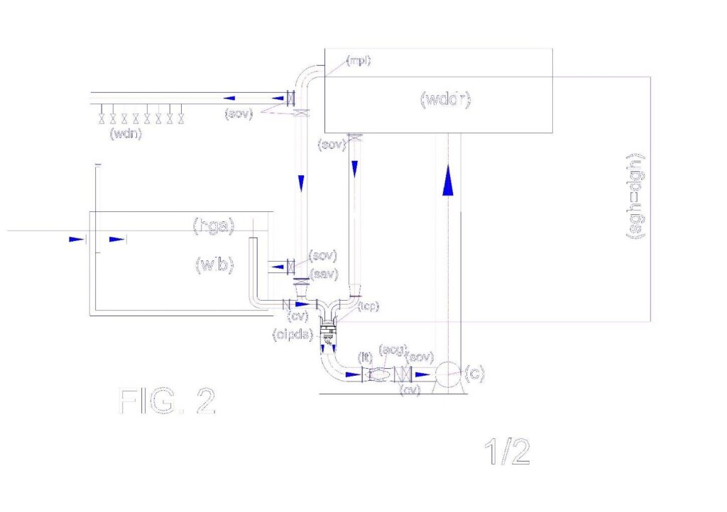
Legenda della Fig. 2: (C) collector; (oipds) overturned intubated pump with dual suction; (cv) check valve; (dgh) delivery geodetic height; (mpl) probe of the minimum or maximum level; (sav) supply additional valve; (sacg) submersible alternating current generator; (sacm) submersible alternating current motor; (sgh) suction geodetic height; (sov) shut-off valve; (tcp) tube containing the pump; (wdn) water distribution network; (wddr) water distribution and disconnection reservoir; (wlb) water lifting basin.
Fig. 1 illustrates how is designed an autoclave system for water pumping, hydro power producer, which reports the following legend:
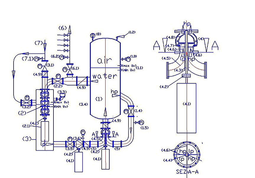
Legend: (1) autoclave pressurized tank; (1.1) level regulator with capacitive probes; (1.2) safety valve; (1.3) manometer with shut-off valve; (1.4) motorized valve flow control with position transmitter; (1.5) pressure flow transmitter; (2) pump used as a turbine (pat); (2.1) alternating current generator submersible; (2.2) motorized valve to supply turbine with flow adjustment; (3) water transit tank at atmospheric pressure and containment pat; (3.1) motorized valve to feed pressurized water network; (3.2) motorized valve bypass supply at low pressure; (3.3) air valves; (3.4) Water level control with capacitance probes; (3.5) motorized valve for water supply at low pressure; (3.6) feed electric pump in low pressure variable speed, driven by an inverter (4) electric dual supply pump on the suction side; (4.1) pump drive motor, with variable speed, controlled by an inverter; (4.2) joint pump motor coupling; (4.3) transmission shaft; (4.4) tube for protection of transmission shaft; (4.5) double curve with septa crossed separators in low pressure (LP) and high pressure (hp); (4.6) septa to flow separators; 4.7 closed impeller; (4.8) pump diffusor; (4.9) check valve. (5) flow diverter stub pipe; (6) water distribution network; (6.1) motorized valve to feed water distribution network; (6.2) pressure flow transmitter; (7) water supply line; (7.1) pressure flow transmitter; (8) electrocompressor.
As can be noted from Fig. 1, the autoclave pressurized tank (1) is fed with water coming from the tank (3), which is supplied from the water supply mains (7) and with the recycled water from the same autoclave tank (1). Contrary to existing autoclave systems, in this system, the pumps and turbines are always in operation and are the valves to divert the flow where it is needed. If the water distribution network (6) requires water, it gradually opens the valve (6.1) in function of the milliamps signal of a flow rate or pressure transmitter (6.2), in fact, the automation can be achieved in both ways: if there is a drop in pressure or the detection of a flow rate, we have to increase the degree of the valve opening (6.1) until the pressure or the flow rate stabilizes. When the pressure in the network rises to the nominal level or the flow stops for the closing of the network valves, the valve (6.1) closes. With the valve (6.1) closed the entire flow of water circulating in the system is diverted, by the valve (2.2) into the turbine or pump used as turbine (pat) (2), shown in the figure, which discharges the water in an open tank equipped with air vents (3), which, in turn, by means of a valve (3.5) and a circulation pump at low pressure, feeds a mouth of a pump with a double feed (4), while the second mouth is directly fed with the maximum pressure of the pressurized tank (1). The pressurization with compressed air is supplied from the compressor (8). Since the flow variable, the valves can be partially opened, so the water circulates where you experience the pressure drop compared to the nominal values, detected by flow rate or pressure transmitters located near the valves themselves. When there is taking of water from the network (6) there is a drop in pressure in the tank (1), which is immediately restored both through the initial operation of the compressor (8), both allowing water into the supply circuit of the tank (3) from the public supply network (7). This supply can take place through the supply valve (3.1) if the valve (2.2) is closed, or through the valve (3.2), if the 2.2 is partially open. The power supply is stopped when the electronic control controller (3.4) indicates the maximum level in the tank (3).
Obviously, this system produces the maximum electrical energy when there is no withdrawal from the water supply (6), for example, in the night hours. In fact, in such conditions, it produces energy without consuming the water that circulates between the two tanks. Consequently, does not consume even the compressed air, apart from that which is liberated into the atmosphere when the water is vented to atmospheric pressure in the tank (3), but this phenomenon is quantifiable as milligrams of gas per liter of water (nitrogen , oxygen, CO2) according to Dalton’s law of which is provided below the main formulas that explain the concepts, without considering the merits of the calculations:
In fact, in a mixture of ideal gases contained in a volume V and the temperature T, the molecules of each gas molecules behave independently from the other gases; as a consequence of this is that the pressure exerted by the gaseous mixture on the walls of the container and on the water surface is given by: where, R is a constant that that is 0,0821;
, … represent the number of moles of each component of the mixture. This law is valid under the conditions by which it is valid the ideal gas law is approximated at moderate pressures, but becomes more and more accurate as the pressure is lowered. By defining the molar fraction as the ratio between the number of moles of the ith component and the number
Total of moles present:
It is obtained that in a mixture of ideal gases, the partial pressure of each component is given by the total pressure multiplied by the mole fraction of that component:
.
In essence, for each gas present in the air is possible to calculate what percentage is solubilized in water at the working pressure, but for practical purposes, the energy that will spend to compress the air will be a small expense, since the air compressed, not ever coming out from the volume of the tank (1) has only small pressure fluctuations, and once it reached the saturation point not dissolves more air. One that is consumed is due to the lower water solubilisation of the gas, at atmospheric pressure. In fact, when the water passes through the tank (3), provided with air vents, releases a small portion of air, which becomes insoluble to the atmospheric pressure, which comes through the vent (3.3). But, obviously, the transit times in this tank are very narrow and the complete air expulsion process can not occur, because, immediately go back into the water tank (1) where the gas can not escape from the surface of ‘water, returning again to the maximum solubilization conditions.
Therefore, as mentioned in the introduction, a pressurized circuit with autoclave (1), coupled to a turbine (2), to an open water transit tank (3), to a water recycling pump with double feed ( 4), can operate in a very similar way to a circuit in an open vessel kept constantly full, shown in Fig. 2, even if it uses some different physical principles. In fact, in both circuits we can produce energy also lifting the water, provided that the water to be lifted are inserted in the recycling loop, always full, of the basin provided with a top hydrostatic pressure, entering from a suction inlet of a pump with a double feed. In fact, in this case, in the circuit in the open vessel the water comes out raised to overflow from the upper basin spending only the energy for the recycling, no lifting of about twice the maximum flow rate which can go out of the weir. The same thing can be said with the autoclave with pressurized circuit, even if the water levels to maintain constants are two: one in the autoclave tank (1.1) and one in the transit water tank at atmospheric pressure (3.4). Obviously, in order to constantly maintain these levels in the autoclave with pressurized circuit you are required a computerized management of the degree of opening of the motorized valves (1.4 – 6.1 – 3.1 – 2.2 – 3.1 – 3.2 – 3.5), the adjustment of the speed of the motors (4.1) of circulation pumps with single and double power, and, if necessary, also the commissioning of the compressor (8). But the complexity of the circuit is largely compensated by the energy from the energy saving and production that we obtain by means of this special hydraulic circuit, which is not against the principles of conservation of energy, but enhances them, exploiting synergies between the same, together with the compressibility of the air and the not compressibility of water. However, the heart of the system is the pump with double feed (4), without which it would be possible to circumvent the force of gravity in an open vessel (Fig 2) and the pressure of the autoclave (1) of Figure1. But it is also important to the way in which it feeds the pump that has to start from a certain distance from the pump, so that in the inlet section of the pump represented by the section A-A of Fig. 1, we have four separate streams of which two high pressure (hp ) and two low-pressure (lp), arranged diagonally to balance the hydraulic pressures in the impeller and the bearings. In order that this separation of the flows can take place it is necessary to start from the flow diverting (5) logs in that the double curve with separator baffles (4.5), must already receive the stream channeled into the correct position, so that it may cross as shown in section. A-A. Then, the half of the particular curves (4.5) using only half of the passage section, already arranged diagonally, that flow in only one input section of the pump already divided into four sectors seamless up to the fins of the impeller. In fact, with this type of supply, when the impeller is rotating, receives in the same quarter section, flows of water with the alternating sequence hp – lp, using the water thrust with higher pressure (hp) to push forward, the water with less pressure (lp). On the other hand this hydraulic principle is already used in multicellular pumps, where the water retains its total dynamic pressure (flow rate * unit pressure * the passage section), and increases from stage to stage, entering the center of the impeller , exiting at the periphery of the same, and returning to the center of the next stage, to effect, in particular, of the strength of the total dynamic pressure that follows the path of the impeller blades (4.7) and the diffuser of the pump body (4.8), as shown, with arrows, in the enlarged detail of the pump (4). In particular, to generate energy, from static water in the open tank or closed and pressurized, it is necessary intubation of the flow and pressure in a section of a one-way flow passage, without solution of continuity with the profile of the impeller blades. With the increase of the working pressures it is also important to the accuracy of machining, which prevent leakage in the reverse direction to the flow. In fact, the multi-stage pumps also reach operating pressures in unique sense of hundred bars.
As is known, the applications of hydraulic lifting pumps are endless. Sometimes you need very large flow rates with very small heads, for the defense of the territory and at times very small flow rates with high prevalence, for the most distant lifting from the water supply source. This resulted in a remarkable variety of pumps and impellers, which are produced throughout the world, being the lifting of water, along with transport, the largest energy expenditure of the planet Earth. Unfortunately, much of this growth is due mainly to the absence of the reflection that led to the conception of the pump with double feed that primarily uses the gravitational force, the principle of communicating vessels, the principle of Pascal, the Torricelli’s theory, instead of engine power coupled to the pumps. In fact, the pumps have been designed to overcome the forces that oppose the circulation of the water, independently of the energy required. Today it is no problem to build engines with a power exceeding 3000 kW, powered by 6,000 or 9,000 volts, to be coupled to the pumps. Today, large pumps, large motors, large turbines, are a credit technology, while large water projects with large dams are a credit to the construction engineering. It ‘difficult for the experts admit that this type of development has been wrong from the ground because the pumps would have to be designed to get the forces that oppose the lifting of the water, as indeed, was the case in mechanical lifts. In fact no one raises mechanical lifting weights directly, but does so through many systems that reduce the effort (inclined planes, rolling friction, reports belt drive, gear, etc.). Queste sono le ragioni fondamentali per le quali il sottoscritto ha studiato soluzioni idrauliche alternative per risparmiare energia. E’ stata una sorpresa, per lo stesso sottoscritto, scoprire che questi impianti si possono trasformare da grandi assorbitori di energia in produttori di energia, per la differenza tra l’energia spesa è quella prodotta, inserendo in tutti gli impianti delle turbine idrauliche. In all cases the pump is indispensable with the dual feeding on the suction side, which shows, through one of the mouths, at the entrance of impeller, the maximum dynamic pressure of the circuit, so that, as in the case of the last stage of a multi-cellular pump , the impeller must only provide a small part of the energy to ensure the continuity of the flow, and allow the feeding of the turbine with the maximum pressure allowed by the open system or with pressurized autoclave. In any case the exit of the turbine, if there is kinetic energy, the only opposition to the water circulation is calculated in proportion to the output speed (V2 / 2g), since the static pressure of the pressurized reservoir or tank do not oppose to internal circulations of the stored volume of water. La pompa con doppia alimentazione sul lato aspirante, serve soprattutto a miscelare due flussi con portate simili ma pressioni diverse, affinché la pressione maggiore si possa espandere nell’intera sezione di passaggio, la quale, ovviamente, deve essere almeno il doppio, di quella in ingresso, delle singole sezioni, se si vuole trasmettere l’intera pressione al doppio della portata.
At the current state of the doubling of the flow rate in a pressurized system it can only be done by inserting in parallel two electric pump with the same characteristics. But in this way they will also double the energy consumption. With the invention of the pumps with double feed and relative power supply circuit, making out the water raised by the overflow of the installations and reintegrating the same amount from the suction side of the pump, the plants behave as recycling plants in a vase filled always open , or in recycling circuits pressurized with autoclave. Therefore, the energy required for lifting is not that of current systems, but the one calculated by using the load losses without lifting water, which is usually hundreds of times lower. Suffice it to say that a piping DN 1000 with a flow rate of 1000 L / s, a water velocity of 1.27 m / s according to the tables calculated with the formula of Bazin-Fantoli has a load loss of only 1.5 m / km. Therefore, with the energy spent to lift of 1.5 m, 1000 L / s, we can move the same flow rate to a kilometer of distance in the horizontal, which is equivalent to the equivalent length of a recycling circuit much more complex than those shown in Fig. 1 and 2. Therefore, it pays to double the flow and producing plants always full of water, open or pressurized with pumps with dual supply, even without any energy production, but more so, the solution is not to call into question if ‘ plant can become a producer and not consumers of energy.
From the above description, it should be evident that the pumps must adapt to installations that serve from an environmental and energy point of view, while today plants are adapted to the performance of the pumps, which, despite being much improved yields and for performance, they may not exceed the original vices, which have not probed the possibility of circumventing the gravitational force, in open circuits or pressure with autoclaves, with this simple modification, which starts from the outside of the pump and can not not work. You just have to experience the performance for various types of impellers and the full range of pressures because the applications are endless.
For the construction characteristics of a pump with a double feed on the suction side, it is necessary that both feeding mouths are equipped with a positive hydrostatic head. Therefore in the case of small plants, with little geodesic inlet height, as in Fig. 1 has been provided an additional pump with single supply (3.6), which slightly increases the dynamic pressure on the pump suction dual fuel (4) , with the same flow rate, synchronized with the same, by means of an inverter connected to the drive motor (4.1). As seen in the diagram, Fig. 1, all the water that does not go towards the distribution network (6) passes through the turbine (2) producing energy, without leaving the plant. In fact, the momentary output of the water at atmospheric pressure is needed to produce kinetic energy into energy of compressed air pressure at the expense turbine, in the same way in which in Open vessel circuits produces energy by exploiting the high position of the waters of surface. But since the same amount of water, by means of pumps (3.6) and (4), the control valves, of the level reintegration and the automatism of the control system, immediately comes back into the tank (1) without to do expand the pillow of air and lower the pressure, this plant continues the energy production even during the feeding phase of the water network (6), in the same way in which the diagram of Fig. 2, feeds for overflow the water network to gravity. Infatti, nell’impianto autoclave produttore di energia, il contemporaneo mantenimento costante dei livelli dei due serbatoi (1 e 3), non comporta sollevamenti idraulici, ma solo circolazioni, pur assicurando la pressione di esercizio dell’autoclave. Obviously, if you exceed the capacities for which the plant was designed and levels (1.1 and 3.4) are not maintained, the pumps (3.6 and 4) must increase the number of revolutions and the compressor must compress the air that is expanded, so it is restored the rated operating conditions, that a properly designed system allows a low consumption and high energy production.
Without the exploitation of these natural energies (gravitational force and compressed air) and without the technical features, which are not few, considering that in one hundred and fifty years of industrial development, these innovations were never realized. In fact, these innovations to be efficient must take place simultaneously. It is not sufficient to put under the head of a pump without intubate from the surface to produce the dynamic pressure, as it is not sufficient to separate the flows of a pump with a double power if you do not enter into the pump body, touching the vanes of the impeller, also can not be put the pumps in parallel, as in the traditional lifting systems, but will need to place in parallel the complete plants, as represented in the diagrams of figures 1 and 2, since they do not exploit the static energy but that dynamic individually produced by the same plants, drawing from external sources, which in the case of Fig. 1 are the public water supply (7) and the atmospheric air that is compressed by the compressor (8), while in the case of Fig. 2, the external sources are the hydrostatic levels of the basins always full (wddr) and (wdn) and the gravitational force. It may seem strange, but even the pumps and turbines have never been put in series in the same facilities, since no one has thought that in the same volume of water you can use different hydraulic regimes in the descent phase of water to produce energy by means of the turbines, which discharge at atmospheric pressure (also under the head), while the water ski in a full basin is always a simple pressure drop at the outlet, regardless of the hydrostatic head or pressure of the air cushion. All these innovations have never been put together because the state of art has stopped at the pumps that raise the water against the gravitational force and the turbines that produce energy using the hydraulic jump, in which coincides simultaneously the drop of static and dynamic pressure. The experts have not considered that contemporary fall of static and dynamic pressure occurs in special cases that have already been exploited almost everyone on the planet Earth, even implementing large hydraulic works, with dams and reservoirs.
Today we must begin to take advantage of the normal cases of hydropower where the hydraulic jump does not exist but there are simple volumes of static water to be exploited as in Fig. 2, both for defense against flooding territory and to undertake large retail networks water at low pressure, which does not drive out the waters for losses due mainly to the high operating pressures and produce energy instead of consuming it; while for smaller and heights networks, serve the autoclave hydroelectric plants of Fig. 1, which also produce energy, eliminating even the unsteady flow disturbances with the aria pillows of autoclaves, but above all, producing energy, carrying out public services of primary and vital importance with investment and operating costs that are not comparable to any existing energy, including coal, which is the cheapest energy but also the most polluting.
If the authorities and the experts do not feel the need to modify plants, sensing that, through the use of the energy of the water position is possible to produce hydroelectric power, it can not be born a solution that provides the surface water intubation, even the combination of pumps and turbines to win the state of initial inertia and therefore no need to include in thecircuit the dual supply pump. In fact, only after having established the state of the art above mentioned it is also possible to consider the energy state of the art of the pressurized systems. But, as mentioned, in this case, design errors have become endemic, as well as hydro power is based on a particular case, that the experts have transformed into a universal event. In fact, the big water projects with large reservoirs and dams, necessary to produce hydroelectric energy, become absurd if it is proved that we can produce the hydropower throughout with simple hydraulic systems.
The famous experiment of Pascal, has shown that in a closed tank the hydrostatic pressure expands in all directions. Just even a small tube for smashing a wooden barrel. But to produce electrical energy is needed the dynamic pressure which ensures the exercise in time on the poles of a turbine. This application requires adequate passage sections and the continuity of the flow, which in small volumes of water can be secure only if it does not disperse the water and exploit advantageous hydraulic schemes in the energy production phase (water drop or pressure drop ) and thrifty energy regimes in the phase of recovery of the water, without charge for lifting water. In these systems the dynamic pressure is equal to the unit pressure for the passage section for the flow of water, therefore the pump with dual supply must be dimensioned for the sum of the two flow and with a delivery passage of a large section, which returns to autoclave, as in Fig.1. In fact, in this circuit on the pump delivery should not win the external resistors to the recycling circuit, as the pressure of the compressed air cushion. The water circulation occurs within the stored volume of water with a very small head of the pump. But the body of the pump has to withstand high hydrostatic pressure, otherwise it falls apart as the barrel of Pascal.
Therefore, suppose to realize a small condominium plant that produces energy by means of a submersible AC generator (2.1) coupled to a pump used as a turbine (pat), which exploits the useful height Hu = 35 m and an electric pump with dual supply DN 150 with a capacity of 35 L / s. Assuming the turbine efficiency is 0.75, by applying the formula Pu = η*1000*Q*Hu/102, we have an energy production 9,0 Kw (0,75 * 1000 *0,035 * 35 / 102). Assigning to the pump a prevalence of 0.4 m and a yield 0,6, the power absorbed by the same, which leads a double flow of that which passes into the turbine, calculated by the formula 0,4 * 1000 * 0,070 / 102 * 0,6 = 0, 0456 KW. While the additional circulation pump (3.6), with a flow rate equal to half, suppository with the same yield and prevalence absorbs half of the energy calculated for the double feed pump (0,0228 Kw). In this case the ratio between the energy expenditure and yield is 131,38 (9,00 / 0, 0685). In fact, the load losses in the descent tube, in the turbine, the special pieces and losses at the outlet, are all absorbed by the dynamic pressure on the pump suction, while in discharge have no appreciable load losses, not exceeding the level of ‘water (which is incompressible). No wonder with this result, Whereas it compressed gases are accumulators most powerful energy, flexible and economical of electrical energy storage.
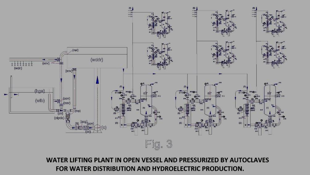
But the plant surprises compared to current solutions for lifting and water distribution are not yet completed as the solutions of Fig. 1 and 2, which do not exist today for amazing scientific, technical oversight, policies and economic, at international level, can be strung together, as shown in Fig. 3. In this figure, for example, the distribution of water of a city or district can diversify the operating pressure using the water distribution by gravity in areas close to the main tank (wddr), while the more distant areas or which feed the highest neighborhoods can be pressurized with air cushions of diversified, without varying the prevalence of the pumps and therefore the power absorbed by the motors, always preserving the ability to produce energy with the water recycling in the individual installations, both at the level of district distribution, that condominium. The computerized management of hydrostatic levels of open tanks, pressurized and valves and a pump speed variable motors can allow very large energy savings and very large energy production, today, unsuspected at state of the art, but easily achievable because the technologies are all existing. Missing only minor modification power of the pumps and the turbines. In fact, even the turbines, as seen in the diagram, can be supplied with different pressures channeled flows ranging up to the blades of the first impeller, which sum the flow rates with maximum dynamic pressure in respect of the principle of Pascal.
The last things to consider are the following:
If to the autoclave systems, power producers we subtract the water distribution network (6), the valves 3.1 and 3.2, we find that not only simplifies the system, but that, even these systems can also be used to produce mobile power, obviously, not on small means of transport, but on those of larger dimensions, since the fairly bulky of autoclaves. But this is a subsequent speech in this application, which can be achieved by pushing to the maximum operating pressure, eventually, using gas even more compressible of air. After all current heat engines have reached its present level of technology after one hundred and twenty years of designs, billions in investment and thousands of patents which was attended worldwide, without solving the original defect in CO2 emissions and particulate matter. If there is a real will to solve environmental problems, the effort that has been done to improve the thermal energy, should also be done by investing in the proposed system, which is much more complete, clean and cheap. In a few years, we will be able to increase the operating pressure and reducing the overall dimensions of the autoclaves. Certainly we can replace a large part of internal combustion engines in circulation on transportation, either by solving the economic problems for the supply of fuels, and environmental ones, due to CO2 emissions and particulate matter. For example, the energy plant condominium calculation with a flow rate of 35 L / s water and a pressure of 3.5 bar, which produces 9 kW / h of power, if we increase the pressure to 35 bar, would produce 90 KW/h; but if we also bring the flow rate to 350 L / sec, it would produce 900 KW / h. Obviously, we are at year zero in this direction, but only because the reflections on this way of producing energy arriving very late and all the experts, public and private, have focused on other energies, which, unfortunately, have already shown to be less efficient, but also less useful, since not to combine with public services of primary importance, such as the distribution of water, the depuration, the dissalazioni, transport without pollution. In the latter case, fortunately, today there are the technologies for feed in the initial phase the pump motors and valves with three-phase UPS. After the start of the system, managing the flow of water with control valves and the speed of the pumps with inverter, we can produce the mobile energy in large quantities, replacing thermal engines and also making unnecessary the distribution networks which, not only require large investments, but also involve security issues and management, and disperse enormous amounts of energy in the air or underground path.
Luigi Antonio Pezone