Capture cooling purification chimneys CCPC (international patent N. Patent WO2014/076724) and Subsequent Invention Air filtration and thermal exchange tower AFTET.
ABSTRACT
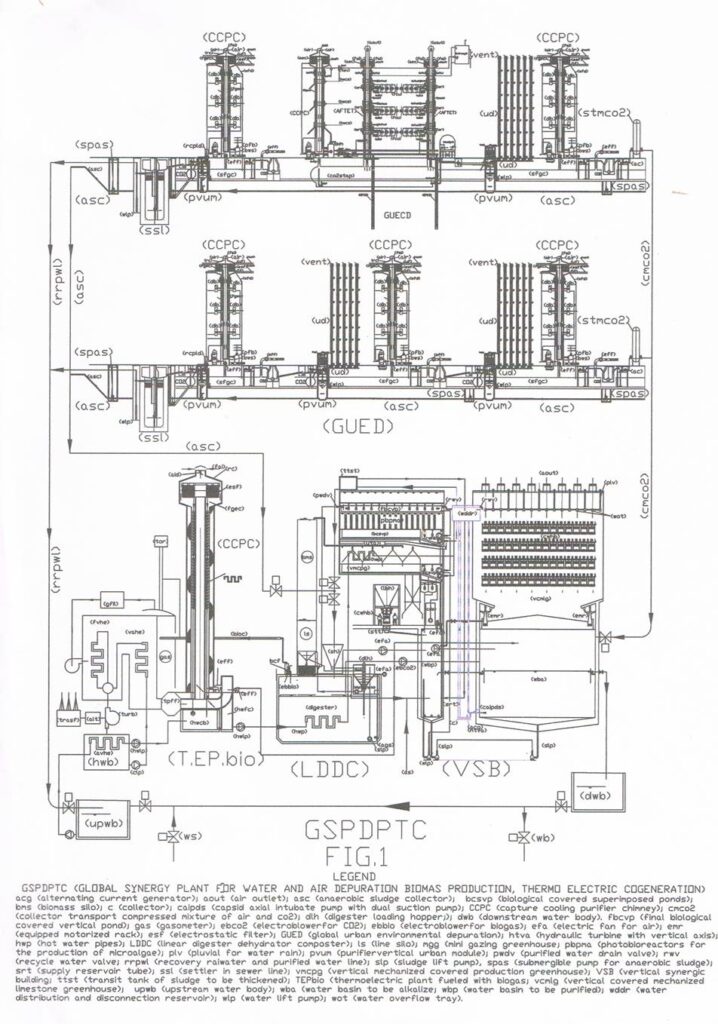
At the state of the art, industrial and urban chimneys are a simple way for the smokes to the atmosphere, since purification of the smoke is realized only in those industrial plants with a filtering system embedded into the plant themselves, while the cooling of the smoke is simply obtained by heat exchangers that pre-heat the combustive air that supply burners and furnaces. The CO2 is a perfectly oxidized gas and thus it cannot be eliminated only by air filtering, nor reduced with electrostatic filtering. Therefore, the industrial and urban chimneys (CCPC) are the first plants that will allow to recover CO2 and, if necessary, to complete reduction of NOx and SOx, ash and part of the heat scattered in the atmosphere. The neutralization of CO2 and most of the components harmful for environment will take place in other plants which follows the capture, but in the chimneys most of the heat can be transferred to the water through a heat exchanger embedded into the exhaust pipes suitably modified. The water so obtained can be used to heat large digesters and industrial greenhouses mainly for energy production, while in the urban setting, mainly for improving the efficiency of household boilers, supplied with pre-heated water. The chimneys (CCPC) belong to a group of national and international patents that can be combined in various manners to obtain the global purification and energy that contributes to protect the environment giving back to the sea mineral salts and carbonates. The fig. 8 shows the chimneys inserted into (GSPDPTC): Global synergy plant for depuration, biomass production and thermoelectric cogeneration, based on several national and international patents of applicant.
DESCRIPTION
The technical fields of this invention are protection of the environment and saving of energetic resources both in industrial and urban settings. This invention belongs to a group of inventions that aim at preventing phenomena of water and atmosphere acidification and recovering of energetic resources, processes that cannot be carried out with current purification and energy production systems. The main invention is the one that integrates into a unique system old and novel technologies to avoid losses. This main invention is named (GSPDPTC): “Global synergy plant for depuration, biomass production and thermoelectric cogeneration”. This request is dedicated just to the capture cooling purification of fumes and not enter into the merit of other processes that remove the CO2 from the flue gas, that will be described in other industrial treatment plants.
The background art in the protection of environment and in the production of energy neglected synergies among different plant types, which, instead, could lead to global purification of the environment. Chimneys are a shortcut that does not allow addressing and solving significant environment problems, because combustion cycles, independently from the fuel used, cannot finish in the current chimneys that simply eject smokes in the atmosphere. They should be subjected to additional treatments so as toxic material and pollutants are not scattered in the environment and, at the same time, resources such as heat and CO2, the main greenhouse gas, can be recovered. The current state of the art allows to foresee in a near future advanced technological solutions, such as CO2 capture through artificial trees or, by means of chemical and electrolytic alkalinisation of large marine water areas, or directly in the thermo-electric plants, with the so-called CCS technologies. Such technologies are basically a chemical cleansing that reduces the heat power, by capturing the CO2, but without neutralising it, therefore it is necessary to compress, liquefy and bury it at about one thousand meters underground into cavities suitably detected. However, such solution can cause seismic risks and dangerous gas leakage, known as “Nyos effect”, for a similar episode happened in 1986 as found in many publications. On the other hand, CO2 capture directly at the source through the chimneys (CCPC), together with following treatments, will be a real breakthrough, because it currently is the sole technology, acting at the source, with a complete treatment without any side effect, and it allows heat recovering while avoiding that SOx, NOx and fine dusts reach the atmosphere. If it is true that such components can in principle be treated separately from the CO2, it is true that no treatment exists that is able to stop large concentrated emissions of the coal production of thousands MWh. Some hope could be gained if smaller plants were realized. Current individual treatments did not stop the acidification growth of water and atmosphere that cannot be imputed only to CO2, which, of captured at the source, could become the main resource for global environmental protection.
The disclosure of this invention is divided in two parts that illustrate the industrial application and the urban application of the chimneys (CCPC). Both applications demonstrate that current chimneys are simply pipes that scatter pollutants and heat into the atmosphere, while chimneys (CCPC) are actual sophisticated plants. The chimneys (CCPC) play a relevant role in the environment protection since they avoid dispersion of pollutants and heat in the environment and allow their transfer into plants able of global treatments, namely air and water treatments, which do not exist at the state of the art, as it happens for the chimneys (CCPC) themselves. Said chimneys (CCPC) can be used also in the future when biological fuel is expected to be used, in order to collect heat and smokes in a simple and economically convenient system to produce carbonates to send to the see as well as compost for agriculture in conjunction with global plants. In this application, only the main two applications are discussed: industrial thermal plant and urban building with several floors. But, as said, in the industrial sector the chimney (CCPC) can substitute those of the blast furnaces, incinerators, cement plants, co-generators, while, in the urban setting, public buildings, restaurants. The modifications required to standard chimneys to be transformed into the novel chimneys here proposed are the same for both main applications, with differences only in their dimensioning and accesses for maintenance. In this international application we focus only on what is possible to do directly in the chimney and the use of heated water from the flue gases in the recovery of the same make.
The chimney (CCPC) is very similar to a piezometric tower, even if in urban applications it can be embedded into the buildings for aesthetic reasons. In the industrial setting, it is of larger dimensions and a spiral staircase will be used for inspection and maintenance. The structural characteristics that allow the chimneys (CCPC) to carry out functions different from the current one are the following:
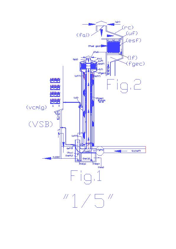
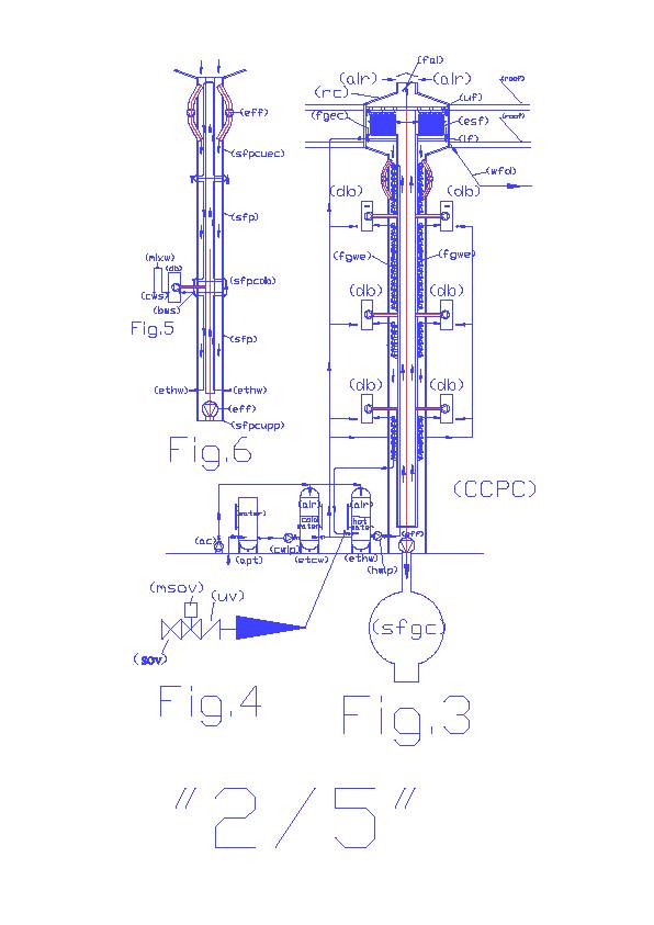
The end where now there is the atmospheric outlet will be enlarged to nullify the speed of the air so as the smoke can be sucked in by the electric blowers (eff). In Figs. 1, 2, 3 it can be noted that all the industrial and urban chimneys can be realized in the version (CCPC), independently from the system they have been dimensioned with (natural or forced ventilation). If the exhaust pipe is well dimensioned (based on the flow rate, the density, the smoke temperature, natural or forced air ventilation), the energy that pushes the smoke up runs out at the atmospheric outlet, where only the pressure due to the lower hot air density with respect to the atmosphere, which can be easily overcome by a flue gas expansion chamber (fgec) and by creating a depression into an external annular gap, concentric with the exhaust pipe of the flue gas, which sucks in the smoke and also some external air through the fresh air intake (fai). For architectonic reasons, the gap can take different shapes, still functional, side by side with the exhaust pipe subjected to a (fgec). The smoke, sucked in by the electric blower (eff) must pass through the electrostatic filter (esf). The characteristics of the electrostatic filters are well known since 50 years. They are able to capture the dust, unburned gases, oxides such as NOx, SOx, CO, which are composed by molecules with null electric charge, but through a high intensity electric field between the electrodes where the air flows at moderate speed, are electrostatically charged thus causing their precipitation on the collecting electrodes connected to the ground. The electrostatic filters are periodically mechanical shaken to let the dust precipitate. Without entering into the construction details of the filter, that can be realized with the same size of the expansion chamber (fgec), which has a relevant functionality and it is positioned at the top end of the exhaust pipe. It is equipped with a removable cover (rm) for the main maintenance operations, an upper floor (uf), that can dismounted too, to whom the filter (esf) is attached and a lower floor (lf) on which dust is collected. In the industrial version fig. 1, where the smoke temperature is very high, and the quantity of dust is higher, a sucking net embedded into floor is foreseen, which brings the dust to a cyclone filter (cf), placed on an external mezzanine, which, working at the same time of the shaking cycle of the filter (esf), collect the dust into a tank at the bottom of the chimney, while the hot air containing CO2, NOx, SOx and the lighter dust is sent to a vertical limestone and photosynthetic greenhouse (VSB) (object of another PCT request), which in the limestone section works as a big scrubber, but with the ability to extract calcium ions from the calcareous material to produce carbonates and sulphates in the water that take away from the environment Cow, SOx, while the photosynthetic section performs the water treatment and biomass production. In the urban version, fig. 3, where the smoke temperature is much lower and the dust quantity is lower, the floor (lf) will not have the sucking net. The dust will be removed by a timed washing process of the floor, with waste water that will be recovered by the new urban purifying system that will comprise the (VSB). In both fig. 1 and fig. 3, the expansion chamber (fgec) is larger than the space occupied by the filter, thus the smoke speed nullifies and the electric blower or the electric blowers (eff), besides the smoke, will convey downwards also fresh air, which will be taken from the air vent (fai) and regulated by the motorized shutter (aid). As it can be seen in Fig. 1 and fig. 4, the mix of smoke and air, still warm, going downward, must brush the surface of the heat exchanger (fgwe) giving some heat to the water circulating in it. The heat exchanger (fgwe) is constituted by common pipes of stainless steel, which start from the exhaust pipe and then the wind up into an annular gap around the exhaust pipe. As shown in fig. 3 and fig. 6, it is possible to embed the electric blower (eff) at the base of the exhaust pipe without being visible from outside and without creating small sucking derivations that suck the urban smog stagnating at the ground, mainly in urban sites with high traffic density. In addition, as shown in drawing. Fig. 1, for industrial settings, and in fig. 3 (sfpcuec) special flue pipe to connect unit expansion chamber, the upper part of the exhaust pipe connected to the expansion chamber (fgec) can be equipped with two or more electric blowers (eff) parallel to the exhaust pipe in order to enhance the sucking action of the electric blowers (eff) at the base.
In the industrial version, of large dimensions, the annular gap is separated by the stairs room by a wall realized with modular sandwich panels of polyurethane coated with a stainless steel shield connected together with special profiles. In fig. 1 it can be noted how the mix of air and smoke purified and cooled is input in the channel (cchwf) from where additional electric blowers (eff) will suck it to input them into vertical synergetic buildings (VSB). Moreover, it can be noted that at the bottom of the chimney can be realized smoke interception dampers (sid1) and (sid2) that allow to deviate the smoke directly into the channel (cchwf), in case of maintenance of the filter (esf), such as at the top end, in case the systems for heat and CO2 recovery are out of order, the smoke can be output in the atmosphere through the fresh air intake (fai) and air inlet dampers (aid).
Fig. 3 reports the urban application of the (CCPC), which substitute the current exhaust pipes. Obviously, in such application referring to plants much less powerful than industrial plants, the plants will have dimensions much lower than in the industrial setting, without the internal spiral staircase, but they can be equipped with the electrostatic filter that can be accessed by the roofs of the buildings or can be placed under the roof to be not visible from outside. Even in this case, the captured smoke is conveyed at the base of the chimney (CCPC) and sent by the electric blowers (eff) to other global urban purification plants. This big urban plant develops underground and captures from the environment also the smog due to the car traffic and with other systems more economically convenient the smoke of the current chimneys but without the heat recovery. As shown in fig. 8, also in the urban setting plants (GSPDPTC) will be included to purify locally water and air together. The production of biologic energy permitted by this complete plant, small or large, belongs to a process described in other international patent. Therefore, the purification path of the chimney (CCPC) smoke is the same as in the industrial setting and it ends in the same way, since also in the urban area or in nearby complete systems (GSPDPTC) “Global synergy plant for depuration, biomass production and thermoelectric cogeneration” can be realized.
From fig. 1 and 3 it can be noted instead that hydraulic schemes that are in front and behind the heat exchanger are very different. This is due mainly to the structural differences between thermal civil and urban plants. But, since the main subject of the patent application the new chimneys that recover the smoke with environmental and energetic aims, it is correct to claim in the same patent all aspects that derive from the smoke recovery in the same type of chimney, independently from the dimension and place where they are used, provided that heat and smoke are concerned. Thus, let us analyse the hydraulic schemes of water flow, separately.
In fig. 1 the recovery and heating of industrial water is reported. It is known that thermoelectric centrals and thermal industrial plants produce huge amounts of hot water, that are used in the cooling systems of condenser turbines, rolling mills, production machines. This water is not polluted since it flows into the plants without contact with chemical or biological cycles, but it cannot be drained into water basins at high temperature. In Europe, the maximum temperature allowed at the outlet is 35 °C. This limit is hardly fulfilled and, in reality, the temperature is higher and this affect water ecosystems. Recovery of such heat seems to be a real resource to be exploited, especially to warm digesters and greenhouses that are the sole energetic source to alkalinize see water.
In Fig. 1, the warm water produeced by thermal plants is drained into the hot water covered basin (hwcb). These basins are not existent nowadays nor they are covered since the heat is not recovered. The way the water is transferred from this basin to the heat exchanger (fgwe) of the chimney is simple: one or more electric hot water lift pumps (hwlp) lift the water directly to a flue gas water exchanger (fgwe), which follows the path of smoke and drains the water into a covered channel for hot water and fumes (cchwf), though a flow control valve (fcv) controlled by a temperature probe, by increasing the flow proportionally to an increase of temperature. The covered channel (cchwf) will distribute the hot water and smoke where they will take part to the purifying energetic process.
Fig. 3 reports the urban hydraulic scheme that does not enter into houses and public places, but it requires only modification of the external system for water supply and the boilers connecting to the existent autoclave plants. These are usually constituted by at least an atmospheric pressure tank (apt) and an expansion tank for cold water (etcw), that is pressurized with air and one or more cold water lift pump (cwlp). To implement the innovation proposed in this application, some new elements have to be added to such components as illustrated in the scheme. In detail, the new components are: an expansion tank for hot water (ethw), a hot water circulating pump (hwcp), a cold water circulating pump (cwcp), an air compressor (ac), then all the pipes needed to connect the heat exchanger (fgwe) to the expansion tank (ethw). The new connections are shown magnified in figs. 4 and 5, where it is important to note the position of unidirectional valves (uv) and that the boilers are supplied by the boiler water supply network (bws), which is fed by the pressurized tank (ethw) at the same pressure of the cold water line (cws) through the common compressor (ac), which resumes air cushions when in one of the two tanks the water raises up to the maximum level. The new network is just the exchanger (fgwe) that extends its path by returning back to the tank (ethw). The water used by this circuit that supply only the boilers is automatically replenished by the tank (etcw) through the unidirectional valve that connects it to (ethw). From this tank, through the hot water circulating pump (hwcp), the water is supplied to the chimney (CCPC) and follows the smoke path, by surrounding the exhaust pipe, thus constituting the exchanger (fgwe), from where start the branches that distribute the warmed water to users, that can be the domestic boilers (db) or the public facility boilers (pfb) or heating units for heating shared spaces (stairwells, halls), which deviate the exchanger path and return back to the heating spiral that terminates in the expansion tank (ethw). The aim of this circuit is mainly to supply the water pre-heated by the chimney smoke to the boilers with a lower temperature leap thus reducing the overall energy consumption. The energy saving can be easily computed by the simple formula E = cs •m• dT, where cs is the specific heat and m the mass of the water, being dT the temperature leap. This means that if we reduce the dT by 25%, then the energy is reduced by 25% as well. Of course, we must take into account the energy absorbed by electric blowers (eff) but these can be handled by temperature probes and inverters for speed regulation and can be helped by boilers with forced ventilation and deflectors used to optimize air and smoke paths for each specific application.
Brief description of drawings. In the disclosure of invention the working principle of the chimney (CCPC) has been described, here after we report, in alphabetical order, the complete list of the acronyms that appear on drawings about (CCPC)
Legend: (ac) air compressor; (af) air filter; (ags) agitator sludge; (ahu) air handling units; (aid) air inlet dampers; (aout) air outlet; (acwhs) arrival cooling water heating system; (asc) anaerobic sludge collector; (ads) anionic detergent solution; (apt) atmospheric pressure tank; (art) anionic regeneration tunnel, (as) arrival sewer; (avhe) heat ewchanger; (aw) agricultural wastewater; (aws) alkaline water supply; (bcf) biogas cyclone filter; (bc) bagged compost; (bcsvp) biological covered superimposed ponds; (bmh) biomass hopper; (bmpc) biomas pneumatic conveyor; (bmc) biomass collector; (bioc) biogas collector; (brse) basket and racks elefator; (bws) boiler water supply; (casrb) covered area sorting racks and baskets; (CCPC); capture cooling purification chimney; (cf) cyclone filter; (clp) condensate lift pump; (CMCO2) collector transport compressed mixture of air and CO2; (crt) cationic regeneration tunnel; (csc) collecting stones channel; (ct) condensation tank; (cwhb) calcareous wheeled hanging baskets; (cwlp) cold water lift pump; (cchwf) covered channel for hot water and fumes; (cws) cold water supply; (db) domestic boiler; (dlh) digester loading hopper; (dwb) downstream water body; (dst) distribution smud tank; (dwt) desalinated water tank; (ebCO2) electroblower for CO2; (ebbio) elettroblower for biogas; (efa) electric fan for air; (eff) electric fan for fumes; (esf) electrostatic filter; (emr) equipped motorized rack; (ethw) expansion tanks for hot water; (etcw) expansion tanks for cold water; (fai) fresh air intake; (fcv) flow control valve; (fvhe) fumes vapor heat exchanger; (fgec) flue gas expansion chamber; (fgwe) flue gas water exchanger; (fbcvp) final biological covered vertical pond; (fgfs) flue gas filtration system; (gf) grating floor; (gw) glass wall; (GUED) global urban environmental depuration; (hwb) hot water basin; (hwp) hot water pipes; (hwcb) hot water covered basin; (hwcp) hot water circulating pump; (hwfc) hotwater and fumes channel; (hwlp) hot water lift pump; (hws) hot water supply; (lf) lower floor; (lbh) limestone boulders hopper; (LDDC) linear digester dehydrator composter; (mgg) mini glazing greenhouse; (pbpma) photobioreactors for the production of microalgae; (pcbio) pneumatic conveying biomass; (plv) rain; (pfb) public facility boiler; (pvum) purifying vertical urban module; (pwdv) purified water drain valve; (pwo) purified water outlet; (rfwt) resins final washing tunnel; (rm) removable cover; (rcpld) road control panel with mini limestone dosing hopper incorporated; (rrpwl) recovery rainwater and purified water line; (rrt) resin regeneration tunnel; (rwt) resins washing tunnel; (rww) resins washing water; (rwhb) resin wheeled hanging baskets; (se) stairwell and elevator; (sfgc) settling flue gas collector; (sfp) standard flue pipe; (sfpcdb) special flue pipe to connect domestic boiler; (sfpcuec) special flue pipe to connect unit expansion chamber; (sfpcupp) special flue pipe to connect underground purifier plants;. (sh) sludge hopper, (sk) skylight; (sid 1-2) smoke interception damper; (sle) sump sludge extraction; (slp) sludge lift pump; (sov); shutoff valve; (spas) submersible pumps for anaerobic sludge; (ssl) settler in sewer line; (STAMCO2) storage tank atmosferic mixture of air and CO2; (STCMCO2) storage tank compressed mixture of air and CO2; (stt) sludge tape transport; (tsp) transparent solar panels; (ttst) transit tank sludge to be thickened; (rwv), recirculating water valve; (TEPbio), thermoelectric power plant fueled by biogas; (TEPfos) thermoelectric power plant fueled with fossil fuels; (tucCO2) thickening CO2 underground collector; (uf) upper floor; (upwb) upstream water body; (uv) unidirectional valve; (vcmlg) vertical covered mechanized limestone greenhouse; (vclmg) vertical covered limestone mechanized greenhouse; (vahe) heat exchanger; (vm) vertical mixer; (vmcpg) vertical mechanized covered production greenhouse; (VSB) vertical synergic building; (wb) water body; (wba) water basin to be alkalize; (wbc) water cooling basin; (wbp) water basin to be purified; (wfd) washing floor drain (wlp) water lifting pump; (wodc) water overflow and drainage channel; (wot) water overflow tray; (ws) water supply; (wss) water sofned supply.
The drawing “1/5” shows fig. 1 that is the complete section of a chimney of a large industrial thermal plant, which can be not only a thermoelectric central but also a steel plant, cement plant or an incinerator. In detail, it can be noted the input of the flue gas and water (ws), the output of the flue gas from the (CCPC) through the electric blower (eff) and of the hot water through the valve (fcv), that go into the common covered channel (cchwf), from where the hot water supplies the digesters (LDDC) and the flue gas supplies the sections (vcmlg) of the (VSB). Fig. 2 shows the magnification of the expansion chamber (Fgec), where the path of the air is visible which enters into the chimney and the smoke coming out of the exhaust pipe.
The drawing “2/5” reports a generic connection to the sewage system, in which fig. 3 is inspired to the scheme of a global urban purification system. It shows that global environment (air and water) protection can be obtained as well as recover the heat lost by the smoke in the domestic plants. Fig. 4 shows the details of the connection between pressurized tanks of cold and hot water, while Fig. 5 shows the separated connection of domestic users (bws and cws) to exploit the feeding of pre-heated water of the boilers. Fig. 6 shows how it can be achieved the industrialization of exhaust pipes with gap and standard included heat exchanger that can be coupled to each other through male/female connections or flanged: (sfp) standard flue pipe with cavity and heat exchanger built, and special pieces for connection to domestic boiler: (sfpcdb), special flue pipe with cavity and heat exchanger built to connect domestic boiler. Modern gas boilers with flue gas condensation are those which assure the best thermal performance.
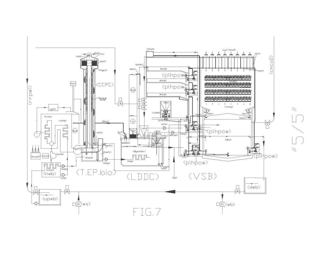
The drawing “3/5”, fig. 7 shows the scheme of a global synergy plant for depuration, biomass production and thermoelectric cogeneration) in which there are the industrial version comprising: 1 (TEPfos), 2 (CCPC fos), 3 (VSB), 4 (LDDC), 5 (TEPbio), 6 (CCPC fos). Where, (TEPfos) produces fossil energy, heat, smoke and CO2. It transfer the CO2 and the heat of the smoke to (CCPC fos), while the heat of the water goes to (LDDC); (CCPC bio) transfers the heat of the smoke to (LDDC) and the CO2 to (VSB); (VSB) produces biomasses that are transferred to (LDDC) and alkaline water that is sent to the sea; (LDDC) produces biogas that is transferred to (TEPbio), solid digested for agriculture and liquid digested that is transferred to (VSB), while hot smoke with CO2 go to (VSB). At the same time (TEPbio) produces biological energy, heat, smoke and CO2; it transfers the CO2 and the heat of the smoke to (CCPCbio), while the heat of the water goes to (LDDC). The loop can continue indefinitely with a coexistence of fossil and biological fuel that produce clean energy, compost for the agriculture and alkaline water to reduce oceans’ acidification.
The drawing “4/5”, fig. 8, shows the scheme of (Gued), “global urban environmental depuration” integrated in the system GSPDPTC, described above, in which there are the urban version comprinsing: 1 (CCPC), 2 (VSB), 3 ( LDDC ), 4 (TEPbio) that produce fossil and bioenergy, heat, smoke, CO2 and polluted water. The heat of urban (CCPC) goes to (db) domestic boiler, the heat of urban (TEP) and its (CCPC) goes to ( LDDC); urban CO2 from the TEPs and (db)s goes to (VSB). (VSB ) produces biomass, which is transferred to ( LDDC ) and alkaline water that is sent to the sewer system, which will be very different from the current system because it does not produces hydrogen sulphide, but purifies the water and capture CO2 and smog. (LDDC) produces digested solids and liquids, as well as biogas that is transferred to (TEPbio). The digested solid is used for agriculture while the digested liquid is transferred to (VSB). This loop can continue indefinitely with a coexistence of fossil fuel and biological systems to produce clean energy, compost for agriculture and alkaline water to reduce ocean acidification. To obtain the maximum performance from entire system it is required to change the “purifying urban vertical module” (pvum) provided in Gued, so that not only must it be connected together with the anaerobic sludge collector (asc), but must also be placed under a “mini glazing green house (mgg), within which there will be a small section (vclmg) that is used to oxidize and alkalize the waters and neutralizes CO2 without resorting to the use of calcium oxide. This is not always possible due to space limitations in the old urban centers, but it can be located anywhere there is space, such as a bed or a roundabout. In Figure 8, we report (pvum) with (mgg) or a ” Road Control Panel with mini limestone dosing hopper incorporated” (rcpld).
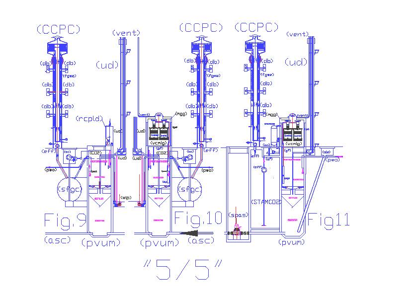
The drawing “5/5” fig. 9 shows a diagram of an original (pvum) purifying urban vertical module, expected in a global urban sewage treatment with “road control panel with mini limestone dosing hopper incorporated”(rcpld). This system can be used in global, urban purification, where there is no space on the surface to achieve the solution shown in fig.10. Infact, (rcpld) can be advantageously replaced by a (mgg) “mini green house glazing” incorporating a section (vcmlg) vertical limestone covered mechanized green house, superimposed on the (pvum). This system is more efficient in local purifying air and water, which is made alkaline by neutralizing CO2 without consuming calcium oxide. In urban areas the system Gued + GSPDPTC, locally, works in the following way: The chimney catches the exit air pollution from boilers and furnaces, having purified the fumes with the electrostatic filter and recovered heat to enhance the thermal performance of domestic boiler (db), the fumes are released in “settling flue gas collector” (sfgc) from which the mixture of air and CO2 through various “air filters” and “air compressors”(ac) compress it in “storage tank” (STCMCO2) and in a network (CMCO2) from which they can fetch both sections of oxidation of local (pvum) that the VSBs basins of oxidation (wba) and (wbp) that exploit the pressure and the oxygen to oxygenate the water, while the CO2 issued by oxygenated waters, forced to climb the local greenhouses and VSB (vcmlg), is absorbed to produce carbonates in the same waters that fall within their respective basins. In (pvum) it can also consume the nutrients, such as phosphorus and nitrogen by means of photosynthesis permitted by stagnant and oxygenated surface, since the treated water forced out of a tube going up to at least 100 cm to reach the level of overflow. Even in (pvum) waters are alkalized in the greenhouse by touching trays (wot) and crossing the baskets filled with calcareous material (cwhb) of (vcmlg), although everything is in miniature, in (pvum) happen the same purification processes of large VSB.
Fig. 11, shows that the main functions of oxidation, photosynthesis and alkalization and the flue gas purification can happen even in homes and businesses or industrial blocks from centralized purification systems, supporting chimneys (CCPC) to (pvum) with (mgg) and (vclmg), but adding a storage tank for the atmospheric mixture of air and CO2 (STAMCO2), storage tank mixture of compressed air and CO2 (STCMCO2) with itsfiltration (af) and air compressor (ac). The sludge produced by (pvum) blocks are extracted by means of a tanker truck through “sump sludge extraction” (sle) and taken to (LDDC).
Industrial applicability. From what reported above, it seems very strange that chimneys like (CCPC) do not exist already today, but there are only simple pipes emitting smoke in the air. From the drawings and explanation it easy to understand the strategic importance of what is claimed here in the largest industrial applications, because it is much more difficult capture on the ground the energy of the heat without supporting the natural ascent to the sky that serves as a first cooling. At industrial level, we cannot talk of commercialization, but at a technical level no thermal plant should avoid usage of (CCPC), even if today this is what happened. The results are under our eyes. Let’s try to imagine the environment if the thermoelectric centrals, the incinerators, the steel plants, the cement plants and all industries took back to the ground the smoke and let them go through the calcareous scrubbers and the VSB. The same applies to the numerous urban exhaust pipes, and in such cases, a commercial exploitation can be envisaged, as described in the drawing n. “2/4”, but additional components would be necessary to collect the pollutants captured by (CCPC). Such components should be structural and the designers of public buildings should take care of this. However, even structural solutions need of technologies that can have an unexpected commercial exploitation. Chimneys (CCPC) belong to this category and this the motivation of such PCT request.
Principal Claim.
1) Chimney (CCPC) for capturing, cooling and purification of smoke, for both urban and industrial application, characterized by the fact that at the top end, where, normally, there is the output to the atmosphere, a flue gas expansion chamber (fgec) is created, which allows to slow down, until nullify, the speed of smoke, that, without kinetic energy, are deviated first in the electrostatic filter and then towards the ground (lf) through a depression created by one or more electric blowers (eff), which force the smoke to pass through large holes in the lower floor (lf) and the annular interspace that goes around the exhaust pipe, where they touch the heat exchanger (fgwe) giving some of the heat to the circulating water; also the external air that enters in the expansion chamber (fgec) from the external air vent regulated by the damper (aid) contributes to the cooling; large industrial chimneys are built of reinforced concrete, while urban areas chimneys with double stainless steel insulated chamber; in industrial chimneys dust captured by electrostatic filters are evacuated from a cyclone filter (cf), while in urban areas chimneys from simple washing of the floor.
The other claims are not reported having only one legal value, not technical.
PATENT DEMAND CE2014A000003 dated 13 – 05 – 2014
AIR FILTRATION AND THERMAL EXCHANGE TOWER (AFTET).
(This patent may be extended to the international level by 13 – 05 – 2015)
Summary
The recent inventions of the gas heat pumps GHP, the exploitation of low enthalpy geothermal energy, the CCPC (capture cooling purification chimney), the PVUM (purifying vertical urbans modul), lead us to revise the criteria for the design of heating and cooling urban areas. The cycle of water-ammonia absorption that occurs in GHP, allows the production of domestic hot water and summer or winter conditioning methane directly with large energy savings and system costs. The combination of GHP to CCPC chimneys (which recovers heat and CO2, they filter the fumes), require modification of existing heating and air conditioning systems to better exploit these inventions, largely unknown. Today it is possible to realize a new system for heating and cooling that takes over the GHP and the CCPC, the AFTET (air filtration and thermal exchange tower) and the GPCG (geothermal pit coated with gres) that, together, constitute the intermediate heat exchange element between the GHP and municipal and industrial interns. With this system it will be cheaper than heating cooling and then we can talk about summer and winter conditioning. These innovations are not only possible but also convenient, being cheaper to retrieve the existing energy that produce the new. Serve three inertial water volumes that also act as heat exchangers, in CCPC, AFTET eGPCG. The first to reduce the thermal jump needed for production of sanitary hot water, the other two to reduce the water and ΔT air conditioning. GPCG exchanges heat with the low enthalpy geothermal energy. New air conditioning systems, powered by natural gas or bio-methane, as you can see from the drawings, you can enter in the system global Detox:GHP+CCPC+AFTET+GPCG+PVUM = GUECD (global urban environmental conditioning and depuration). GMLED+ PVUM + CTE + CCPC +VSB + LDDC+ GASOMETER = GSP (global synergic plant) that produce biomethane to supply GHP, fertilizers for soil and alkaline waters to the sea.
Legend
(aaev) adjustable air exhaust vents; (ac) air compressor; (ae) air extraction; (aec) air expansion chamber; (afaf) additional fan and air filter; (AFTET) air filtration and thermal exchange tower; (aid) air inlet dampers; (aout) air outlet; (apt) atmospheric pressure tank; (asc) anaerobic sludge collector; (caf) central air filter; (CCPC) capture cooling purification chimney; (cfcu) channeled fan coil unit; (CO2stap) CO2 storage tank atmosphere pressure; (cwlp) cold water lift pump; (etrwap) expansion tank and refill of water at atmospheric pressure; (dp) drainage pump; (efai) electric fan for air inlet; (efae) electric fan for air extraction; (eff) electric fan for fumes; (esf) electrostatic filter; (ethw) espansion tanks for hot water; (etcw) espansion tanks for cold water; (ew) external wall; (fai) fresh air intake; (fgwe) flue gas water exchanger; (GHP) gas heat pump; (fcu) fan coil unit; (GPCG) geothermal pit coated with gres; (GUECD) global urban environmental conditioning and depuration; (gwrp) geothermal water recirculation pump; (hwlp) hot water lift pump; (hws) hot water recovery supply; (hwcs) hot water consume supply; (paw) purified and alkalinized water; (pawe) purified air water exchanger; (pcws) public cold water supply; (PVUM) purifying vertical urbans module; (pwo) purified water output; (rp) return pipe; (rw) removal wall; (rwm) rock wool mattress; (sov) shutoff valve; (sp) supply pipe (sphect) standard piece for heat exchange chimney or tower; (schect) standard connection for heat exchange chimney or tower; (sfpcuec) special piece for connection to upper expansion chamber; (sfpchcu) special piece for connection to heating or cooling unit; (tco2pt) transport CO2 pressurized tank; (tpcwsr) t piece for connection water supply and return; (uv) unidirectional valve; (wfd); (pwcp) principal water circulation pump; (wr) water return; (wsh) water supply for humidification.
Description.
The recent inventions of the gas heat pumps GHP, the exploitation of low enthalpy geothermal energy, the CCPC (capture cooling purification chimney), the PVUM (purifying vertical urbans modul), lead us to revise the criteria for the design of heating and cooling urban areas. The cycle of water-ammonia absorption that occurs in GHP, allows the production of domestic hot water and summer or winter conditioning methane directly with large energy savings and system costs. The combination of GHP to CCPC chimneys (which recovers heat and CO2, they filter the fumes), require modification of existing heating and air conditioning systems to better exploit these inventions, largely unknown. Today it is possible to realize a new system for heating and cooling that takes over the GHP and the CCPC, the AFTET (air filtration and thermal exchange tower) and the GPCG (geothermal pit coated with gres) that, together, constitute the intermediate heat exchange element between the GHP and municipal and industrial interns. With this system it will be cheaper than heating cooling and then we can talk about summer and winter conditioning. These innovations are not only possible but also convenient, being cheaper to retrieve the existing energy that produce the new. Serve three inertial water volumes that also act as heat exchangers, in CCPC, AFTET eGPCG. The first to reduce the thermal jump needed for production of sanitary hot water, the other two to reduce the water and ΔT air conditioning. GPCG exchanges heat with the low enthalpy geothermal energy. New air conditioning systems, powered by natural gas or bio-methane, as you can see from the drawings, you can enter in the system global Detox:GHP+CCPC+AFTET+GPCG+PVUM = GUECD (global urban environmental conditioning and depuration). GMLED+ PVUM + CTE + CCPC +VSB + LDDC+ GASOMETER = GSP (global synergic plant) that produce biomethane to supply GHP, fertilizers for soil and alkaline waters to the sea. The main components of this system are:
A) Heat pump gas GHP. By trade, is an ammonia-water absorption fueled by natural gas heat pump for the production of hot water and heating simultaneously until the flow temperature of 65 ° C and chilled water even at negative temperatures. Composed of a circuit termofrigorifero airtight, heat exchanger acting as an evaporator, heat exchanger with the function of the condenser / absorber system of heat recovery condensing flue gas side, with limit thermostat, safety valve against overpressure, pressure switch and thermostat fumes, burner, electronic card with microprocessor for the control of all functions, flow meter, water flow, flame control unit.
B) The chimney CCPC, previously filed with the national and international patent applications mentioned, it is quite similar to a water tower. The end, where there is now the outlet air pollution, will be enlarged to the maximum to zero the kinetic rate of the smoke in transit. In this room the reduction of the speed of the fumes will allow the capture of ashes, dust, CO, SOx, NOx by means of electrostatic filters in the shape of a circular crown, which will be crossed, from inside to outside at a speed below 1 m / s. (powders and gases, such as oxides NOx, SOx, CO, are composed of polar molecules uncharged that in electrostatic filters, via a high electric field between the electrodes where the air passes at a moderate speed, are electrostatically charged causing the precipitation collector electrodes connected to ground). These particles, in the phase of shaking of the filter, fall to the bottom and by means of a veil of water are conveyed in timed drainage bags. The CO2 that has a non-polar molecule, can not be captured by the electrostatic filter, but losing rate of climb in the expansion chamber, being heavier than air, and with the help of the vacuum created in the annular chamber, by the fans (eff), brings down this hot air, CO2-rich, which transfers its heat to the slopes of the chimney and down the tube bundles in it (fgwe), fig 2. The air, CO2 and particles escaped the electrostatic filter will be transported in the tank (CO2stap) placed at the base of the chimney. The chimney CCPC not directly involved in the cycles of heating and cooling recovers but the smoke and the heat they contain, preheats the water consumption of health care (hcws), heats the combustion air (ac) power from (CO2stap) CO2 to (pvum), included in the overall purification process GSPDPTC (PCT/IT2013/000316).
C) The AFTET tower in form and substance and very similar to the CCPC. It replaces air vents provided in the original design of the global urban sewage (GUED = global urban environmental depuration). As you can see from the drawings 1/2 and 2/2, incorporates the vent that expels the air in the atmosphere purified flue gas is separated from the CO2, due to the greater weight of this. As the chimney is fitted on top of an expansion chamber (a and c), where the air enters from the outside through the outlet (do). This air will be filtered by the filter (CAF), which may also be different from the electrostatic filter, but as in (CCPC), is heated or cooled by the tube bundles embedded in the annular chamber concentric with the central pipe. The central pipe of AFTET can be made of steel, such as the tube bundle (Pawe) to facilitate the exchange of heat, while the outer wall, insulated with double chamber, can also be realized in polypropylene. The heat exchange that occurs along the column of the tower between the air purified by the smoke captured by (CCPC), the air extracted from (efae), rising in the central tube, the air introduced from (doing) that flows into the annular chamber and crossing the exchanger (Pawe ) together with the air fed from (efa), (Afaf), (Efai), and then goes back through the central pipe, for the natural draft, Allows thermal recoveries both air enters in the environments, both the water contained in (Pawe), which require less energy for heating or cooling.
D) The geothermal pit (GPCG), connected to (GHP) and (AFTET), is based on heat exchange with the ground. Said “λ” the coefficient of thermal conductivity of the material forming the wall of the well, whose unit of measure is derived from the same Fourier’s law (w/m2) / (m * K) = w / mK.
One of the formulas used for the calculation of the heat exchange through coated pipes is the following: (3) Q = [3,17*(t2 – t1)] / [(1/λ1) log (d2/d1) + (1/λ2) log (d3/d2)].Where Q is the heat exchanged in kW / m * h; λ1 and λ1 are the thermal conductivities of the pipe and coating; d1 and d2 the inner and outer diameters of the tube; d2 and d3 the inner and outer diameters of the coating (m). The geothermal well is provided with a tube made of any diameter, plugged on the bottom, stainless steel, externally coated in the factory with ceramic stoneware by means of the drawing process. This tube is assembled by welding work only from the inner side, as it is lowered into the excavation. On the external side, using the common junction pipe stoneware ceramic glass type without VT, with stainless steel sleeves. After mounting the mouth of the well is closed with a blind flange, which is welded pipe stub for connection to the water circulation, which includes the heat pump GHP and AFTET tower. This is completely filled with tap water (with possible antifreeze). The water circulates to hydrostatic pressure determined by the position of (etrwap) and touches the inner surface of stainless steel (λ1 = 17w/mK) that has the outside stoneware (λ2 = 1.0 W / mK) by exchanging heat with the surrounding subsoil. The circulation pump (wrp) forces the water to rise through the inner tube, coated with polyethylene (λ = 0.12 W / mK). With this solution GPGC increases the exchange surface and the transmission coefficient towards the ground and reduces the surface and the coefficient of heat toward the riser tube of the water to not create a short circuit between the water that comes with that enters into the well. the other two to reduce the ΔT of the water and the air conditioning. GPCG exchanges heat with the low-enthalpy geothermal energy with a speed hundreds of times greater than a geothermal probe, both for the greater exchange coefficient, for both the major surfaces, both for the volume involved. The exchange of heat with the ground is useful, especially, in the starting phase, thus alleviating the jump initial heat and contributing to heat or cool the water with the help of the existing ΔT with the subsoil. But when the Dt becomes negative with respect to the direction in which the heat pump works, a three-way valve excludes the well GPGC from the path and proceed only with the volume of water contained in the tower. In fact, the low-enthalpy geothermal energy was conceived in northern countries, where heating systems are turned on for seven or eight months a year and the subsoil is specially heated by heat pumps using the geothermal probes, carrying out, in the long run, the task of inertial accumulator heat. To exploit the subsoil as a buffer tank takes many geothermal probes, but you also need to space them not decrease the efficiency of the transmission. For periods of less heating, and air conditioning in summer, you should use geothermal energy, by means of coated pits stoneware combined with AFTET towers that take advantage of the fast ΔT also available for a few hours and a few months a year. Is well known that the human body maintains constant its temperature due to transpiration process, removing a part of the water with the sweat. If the humidity is high, the surrounding environment is already saturated with water vapor, for which the sweat does not evaporate. Using ventilation, even without ΔT Dt air, the convection generated facilitate water evaporation and transpiration, helping the lowering of the body temperature and giving a feeling of well-being. Thus, these systems, in the summer period, can also work without the contribution of the heat pump, ensuring, in addition to a certain ventilation ΔT although not reaching the performance of well-being obtainable with the chilled water produced by the heat pump. The result will depend on the depth of the well, the diameter, the volume of total water content in GPCG + aftet and the number of fan coils that will be in operation. The heat transfer is permitted by the stoneware ten times higher than that of polyethylene, perfectly in line with the average transmission of the subsoil, and a DN 400 pipe has a circumference 125 times superior to a probe DN 40. Piping coated steel stoneware ceramic, today do not exist but the major heat exchange performance, corrosion resistance and pressure, may justify the increased cost of production. The internal welding work is essential because the outer joints, only on the ceramic does not guarantee the stability of the pressure and pullout of tubes mounted vertically. Therefore propose coated pipes stoneware by means of the drawing process, already used for coating the pipes with polyethylene. In the present case the bevel will be made at the factory only on the inner side so as not to damage the ceramic coating outside during welding. Being tubes stoneware ceramic products in lengths from about 2 m, the welding apparatus may be fitted from the upper side, after incravattato the column on the outer wall of the tube and stop on the mouth of the well. The type of welding more suitable for small thicknesses, vertical, with the lower heating of the piece, and the one called for short circuit “short arc” mag (metal-arc active gas). The welding torch, the type continuous wire, will be mounted at the end of a tube through which cables pass the tube with the protective gas, the thread of the filler material, the power supply with USB cables of a lamp lighting , with a normal camera and a tinted glass to inspect, check the welding and the process. Being the pipes to be welded stoneware products with tolerances of 2 mm, there is no need for adjustment in height, and the tool resting on the upper end and will only have to be equipped with a small motor with reduction gear that rotates the 360 degrees the torch at the speed required by the welding process. The entire operation, apart from the physical positioning of the tool welding on the end of the shaft can be driven and controlled by a laptop computer which also controls the operating data of the other equipment needed: the continuous welding wire (three-phase or phase) with the feed mechanism and control of the wire embedded. These facilities and the cylinder containing the shielding gas will be mounted on a lightweight easily transportable cart alongside the excavation of the pit.
The Drawing 1/2, fig. 1 gives a schematic diagram of a hydraulic system and air conditioning in summer and winter for public or industrial buildings, which require substantial parts of air. This plant is equipped with air extraction ducts (pe) with adjustable air intake vents (aaev) connected via the exhaust fans (EFAE) to the central pipe of aftet. The fresh air through (do), it is called by fans outside (efa); passes through the filter (caf), descends through the heat exchanger (Pawe) and is taken up by the fans (Efai), possibly by humidified (wsh) and mixed with the recirculated air introduced into the environment through the ducted fan (CFCU ). The heat exchangers contained in (CFCU) are fed with the water (ws) and the return to the return manifold (wr). The water contained in (wr), via the valves (TWV) and (SOV) can be diverted to the (GHP) or at the well (GPCG) to make the entire path of heat exchange, based on the temperatures measured by probes mounted on the return pipe a three-way valve is also placed at the entrance of GHP to allow the mixing of the water flow with return, or even exclude GHP ensuring a circulation of air and water without gas consumption in particular environmental conditions . You may notice the similarity between (CCPC) and (aftet) but also the fact that perform different tasks. The heated water from the heat exchanger (fgwe) of the chimneys is water consumption which serves for the entire year, while that which circulates in the heat exchangers (Pawe) of the towers is recycled water, which according to the seasons , the heat pump (GHP) heats or cools, involving also the water present in the wells (GPCG). The hot water produced by (fgwe) in winter, it is used to power up water through the closed circuit of the tower, the expansion tank (etrap) and the three-way valve (twv). Even the standard elements of aftet CCPC and allow the socket outlet water (ws) and the return (wr) by a special piece (tpcwsr) inserted between the flanges, equipped with a threaded cap, usable, in case of need. The air that circulates in (CCPC) is involved in the combustion process while the air that circulates in (aftet) is air drawn from the outside and from the interior to the premises to be conditioned or heated. The air from various sources is mixed in the tank (CO2stap), when the lighter salt air (aout), releasing CO2 to the difference in weight heavier. The efficiency of the separation of CO2 from the air only depend on the volume of the tanks (CO2stap), the adjustment of the damper (aid) from the scope of the fans (efa), which will have to be adjustable rotation and not provide too much flow in excess of those required by local fans (Efai). In fact, the slope of the clean-up and separation of CO2 to be effective, it must be left to natural fireplaces. Surely, over the towers will be used aftet other vents to the atmosphere, possibly embedded in buildings. To increase the volume of (CO2stap) can also be used basements and local terranei closed tight and sealed by the local authorities.
The plant (pvum), when combined, consumes CO2 producing alkaline water. The reservoir of pressurized transport (tCO2pt) mounted on truck with a compressor, performs the service of the CO2 transport facilities GSPDPTC that will use it to alkalize the treated water the plants more.
Fig.2, shows the details of the heat exchangers (fgwe) and (Pawe) that are embedded in the outer chamber of the chimneys and towers. These can be made of any material according to operating temperatures coupled with male fittings and female, but incorporating the heat exchangers must be provided outside of the attacks, preferably flanged, to be able to pair (schetc) and special pieces (sfpchcu) to connect the inner legs with the flue gas or air to be expelled (EFAE) and exterior rooms with fresh air (Efai), which extract the air from the tower or attachments for additional fans and air filters (AFAT), that the placing. These additional air intakes are required when the building is very high and the only air intakes located above the tower (do) and the filter (caf) are insufficient to meet the full range of air required by the building. Obviously, the air intakes are equipped with internal flow diverters for not short-circuit the supply air with the extract.
The drawing.2 / 2, fig. 3 is a schematic hydraulic and air conditioning systems in summer and winter for private homes, which do not require special parts of air. Therefore, this system has only a fan (fcu), small air extractors (EFAE) connected to the central pipe of aftet, and small fans (Efai) for the fresh air, the veins that called from the outside (efa ) through (do), the filter (CAF), passes through the heat exchanger (Pawe), possibly humidified by (WSH). The heat exchangers contained in (fcu) are fed with the water (ws) and the return to the return manifold (wr). The other functions are identical to those described for Fig 1.
Figure 4 shows how, and aftet the CCPC can be incorporated in buildings or placed against the same without causing excessive environmental impacts. The expansion chambers higher (a and c), which may be incorporated in or under the roofs on the terraces, they are certainly less bulky central air handling and evaporation towers that will be replaced by aftet. Realizing the walls removable media (rm) with Papier Mache for indoor and painted steel for the exterior, not only can you clear the effect of the environmental impact of chimneys and towers, but you can even improve the thermal insulation, costipando of mattresses in rock wool between the walls and the outer surface dell’AFTET. Obviously, the removable panels of the walls removable (rw) must coincide in height with the coupling elements of aftet and CCPC. At the special pieces (sfpchcu) must match the wall elements of equal heights, already equipped with factory holes needed for passage of hydraulic hoses and vents.
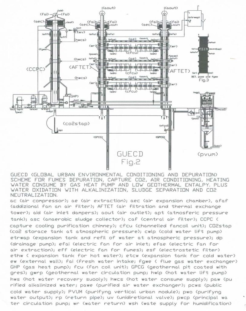
This drawing shows the modification to perform on existing smokestacks for the connection to the system GUECD
Luigi Antonio Pezone