Submerged hydroelectric plants for energy production, oxygenation of seabed and artificial welling
Submerged hydroelectric plants for energy production, oxygenation of seabed and artificial welling
Description of industrial invention CE 2014A000012 dated 06/10/2014
The state of the art in the exploitation of marine resources has been affected by the difficult access to the deep sea offshore and impetuosity of the waves along the oceanic coast. Many have tried to take advantage of the movement of the waves to create electricity but these systems are not widespread because it is very difficult to control the force of the sea surface. Even the simple conveyance of troubled waters towards the turbines involves important and expensive works. It is much more simple and economical gain energy from below quiet hydrostatic pressures. In fact, in this patent are the submerged marine and lacustrine hydroelectric plants that produce electric power, exploiting the hydrostatic head which are undergoing the turbines, without exploiting surface currents and waves. These systems. in addition to producing energy, bringing surface water in the depths, helping to cool the planet, but having the water even more oxygen than is present in the seabed, especially if it is contaminated, they even purifying effects and lead to the lifting of the waters below (upwelling) that bringing to the surface the sedimented nutrients and carbonates by increasing the superficial biological life, consequently, also the production of fish food.
But the importance of this invention is mainly to have found the way to exploit the planet’s largest energy source, which is infinite and clean that no one has ever thought to use, although, there are basic principles of physics that confirm these intuitions. In fact, by applying the law of communicating vessels is possible to fill water in a submerged pipe, of any shape, length and dimension, and inserting along the route of this tube an electric pump and a turbine, we can apply the same rules on the principles of conservation of energy theorized by Bernoulli. In fact, in the sea and Lakes water spontaneously moves from one place to another, and even drops and rises to the surface if it finds grounds profiles that favor these movements. Much is due to the action of the wind which behaves like a big pump with very low prevalence. Therefore, using the same principles with a machine called pump we can focus on delivery and head in submerged tubes to create great currents of ducted water within the same basin between the surface and the seabed. These intubate currents descend deep into the action of hydrostatic head and atmospheric pressure, the pump serves only to displace the water in the bottom area, so that the upper area can go down more easily. The pressure energy in the Earth’s atmosphere is easy to understand because it is identified with the height difference between two reservoirs located upstream and downstream of the turbines that generate electricity. But the work done to produce energy is one-way only goes in the direction of the atmospheric pressure. In fact, if we bring up the waters that we use to produce electricity, we should spend much more energy than is produced. In the aquatic environment the system is more extensive: If you move a quantity of water fifty feet deep, the place of that water is occupied by other water without the upper basin becomes empty, as in a closed circuit. But in the closed circuit is not required to overcome the atmospheric pressure, to circulate the water, we have to win only the pressure losses due to the length of pipes, that are minimal compared to the labor force that serves to overcome the atmospheric pressure. But, as we said, our circuit is not closed but submerged and subjected to a reservoir of infinite size, which do not recycle the same water but the reintegrates immediately with the surface water in any amount due to the principle of communicating vessels, which keeps uniform the upper level. Therefore, we have not to win neither the losses in the circuit, if the circuit is open, completely immersed in the basin, and hydraulic resistances are under adequate water level. In fact, since the plant entirely intubated, the water that move the pump to the seabed can not be replenished from the sur rounding water, it have to be replenished from above, entering in the upper funnel cone (ufc). Therefore, the water that feeds the pump and the turbine is separated from the surrounding water and can concentrate the hydrostatic pressure and the kinetic energy of the pump on the impeller blades of the turbine with the same force that would act in hydroelectric plants on Earth. In our case, hydraulic resistances are on outlet of the pump that is used with the suction side facing up. Hydraulic principles of Bernoulli say that the water level on the suction side of the pump is defined positive head and is subtracted in the calculation of the total head of the pump. So even in submerged intubated plants the positive head performs its action to overcome the pressure load on the delivery of pump, but it is a static force, can not start the water circulation alone. We need of the circulating pump, as in terrestrial gravity plants we need to open a gate valve. As in terrestrial plants by closing the valve stops the hydroelectric plant in submerged plants, stopping the circulating pump (dipc) shuts down the entire system. In this case the movement will stop after a long time since in the system pipes submerged happen phenomena of natural circulation that behave as siphons. All this reasoning may seem at odds with the laws of physics, but we must also consider the infinite differences between sections of the inside of the tube and the surface of the basins. The depression created by the pump suction side, creates inside the tube a small circulation of water (relative to the size of the pelvis) favored by atmospheric pressure and by positive head on the suction side of the pump. Although, in theory, the same hydrostatic pressure also acts on the outside of the pipe and the outlet port of the circuit, cannot oppose the full force on a small section as the output of the turbine, where is concentrated the kinetic output energy, to lock it. It can only dissipate the residual kinetic energy of water with upward hydrostatic force that is spread over the entire cross section of the dock, being water a incompressible liquid that takes the shape of the envelope that contains it. This means that it does not oppose any resistance to concentrated kinetic energy in the output section of the turbine. To those who say that this system cannot operate hydraulically, it can be said that the only system that could oppose the circulation of water in the flooded turbine is to oppose on the same another pump and another intubated circuit acting in the opposite direction.
So, not having to win with the pump any resistance in the circuit, but only to ensure the circulation, it’s no wonder that by spending only a few Kw (4000*0,2/102*η = about 10 kw), marine or lacustrine hydroelectric plant, located fifty meters deep that circulates 4 m3/s creates an electricity about one hundred and fifty times higher. But the energy gain can be even higher, further increasing the depth of installation of the system, of course solving other problems of strength of materials and hydraulic seals. Even where there are no Lakes and seas will be convenient produce energy in reservoirs deep with constant water level, which recycle the same water exploiting the entire positive head. This is certainly more economical of the two reservoirs, at different heights, with external pipes and ancillary works which, however, cannot ensure the constant supply of water for the entire year. All other energies cannot benefit of this powerful energy storage. They need to develop physical and biochemical processes much more complex starting from scratch, and therefore cannot compete in terms of economic and efficiency with this solution. In fact, producing energy with hydroelectric submergible plants that would involve immense water flow without heat them but cooling and oxygenating the seabed in a few years we can repair the damage caused by two hundred years of wrong thermal plants. Notwithstanding that a part of the energy we have to transform with organic thermal plants to produce fertilizers, bio fuels and purify the agricultural sewage, industrial and urban, there is no need to steal land to agriculture and even methane wild extraction processes as the fraking. After this invention, the costs of extraction, purification and production of fossil energy can’t compete with the submerged hydroelectric plants, that avoid the large civil works like the water upstream and downstream of traditional hydropower plants and the water conveyance of works to harness ocean currents and rivers and also carry out important environmental functions that no other world energy can ever accomplish simultaneously producing clean energy. From the publication in network http://www.siallerinnovabili.it/741/energia-idroelettrica-costi/ I extract the following tables which compare the costs of renewable energy:
low head hydroelectric (oltre 10 MW): 11,8 €c/kWh;
wind power in MT: 12,5 €c/kWh;
wind power in AT: 13,6 €clkWh;
direct combustion of biomass: 23,4 €clkWh;
photovoltaic (da 40kW a 1MW): 41,0 €c/kWh;
domestic photovoltaic (1 a 3 kw): 50,0 €cikWh;
Cost components for hydroelectric plants in percentage:
insurance rights and cost of water 10%
cost of the masonry works 40%
cost of works for water supply and discharge 10%
cost of electrical works and control 30%
cost of hydraulic machinery 10%
Totale costs 100%
If we consider that in submerged hydroelectric plants the first three cost items representing 60 % of the total cost, we can safely say that the cost of hydroelectric energy that is already the lowest can reduce of 50 % compared to current costs, with benefits of cleansing that this solution allows and with the possibility to extend them to cover the entire global energy production not having limits due to the characteristics of the territories and from the quantity of water available.
Therefore, the cost of submerged hydropower will not exceed 6,00 €c/kw. If we compare this cost with the average cost of electricity produced from coal, which is about 9,5 €c/kw without C.C.S. and will become 13.6 €c/kw, with C.C.S. (http://www.skepticalscience.com/true-cost-of-coal-power.html) that does not solve any environmental problem in addition to the reduction of CO2, an objective examination, this simple invention is the most important invention environmental and energy of all time. But the undersigned, who came to this solution starting from the purification systems and synergies with other technologies confirms all the other previous proposals unheard because if we combine the use of fossil fuels in the right proportion with the production of biological energy, in the same plants, without CCS , we can also obtain good results of the thermal front and cost around 10 €c/kw, Even in that case protecting the environment by sending carbonates in the oceans and producing fertilizer for the land. But this speech has been tackled in vain in other projects the undersigned.
To achieve submerged hydroelectric plants, in addition to the turbines, of crucial importance are the water pumps to be used, such as turbines, must be ducted, not only because it is the best solution for water circulation, but also to protect from large fish species that could put them out of operation. For that and other practical reasons were chosen axial pumps intubate, which to work should be only fell within the lifting pipes, putting on a ring soldered inside the tube (srdp). Even these pumps must be adapted to submerged implants to be installed at depths much greater than those current and as said, with the suction upwards, contrary to what happens in the current terrestrial plants.
Another important element to consider is the floating system, which must be submerged to not be affected by the waves. Today, there are modular floating polyethylene coupled vertically and horizontally by means of profiles in galvanized or stainless steel, with dimensions 3500 x 2000 x 1000 mm, average density 935 kg / m3, with a buoyancy for each element submerged 5325 kg. These modules can adjust the thrust if filled with water or air. I’m already used to make floating houses, yards and marine lakes, temporary roads etc. Assuming that for the realization of the supporting platform (sbp), The weight of the pipes, the pump and the turbine will have a total of 50.000 kg. it will take about N 10 floats (50.000/5325) which will cover approximately a total area of 70 m2. These modules will distribute them on two plans to build a floating platform of approximately 40 m2 including the stiffening and containment structures. At the center of this platform are realized the holes for the passage of the suspension tubes of the plants. After the installation of the systems the floats are filled partially with water for carry the submerged position in water as shown in the drawings. Among the many types of hydraulic turbines on the market have been identified two types that best approximate the characteristics of the facilities by 1-2 MW, easily achievable along the coastal areas and lakes with low manufacturing costs, very low operating costs, high efficiency, energy and purification, using energies of pressure that is the true infinite energy reserves worldwide, always existing and never used. I will not mention the brand and type of turbines but only the functional aspects since all the turbines can be used in this system. with any flow rate and any pressure drop:
1) Reaction turbine with radial flow, vertical axe, axial exhaust, distributor with adjustable blades (but adjusted at the factory) and fixed-blade impeller. Flow rates from 4 to 100 m3 / s, jumps from 10 to 400 m.
2) Intubated reaction turbines with capacities from 1 to 8 m3/s, jumps from 5 to 100 m (currently 15 m) and alternator pond built.
- Being very different these turbines, also the plant engineering solutions are different. But first, here is a general criterion for sizing the hydraulic turbins, which primarily require the following parameters
- The volume flow Q [m3/s]
- The Fall useful in pressure HU [m]
From this data, you can get the machine characteristic number K. Statistical diagrams of brands include fully functional and geometrical parameters of the machine as a function of K. The adjustment of the turbine is carried out by varying the inclination of the blades of impeller and of the distributor. In this way varies the flow rate through the turbine and the fall of the plant. But in the cases that we consider we will always have a constant level and the flow can be established in advance. We can realize simple machines set at the factory with distributors and impellers fixed to minimize the possibility of a fault, since the submerged implants must not be subjected maintenance. At constant speed of rotation, with certain inclinations of the blades of the distributor and the rotor is possible to calculate the value KU1, which in turn allows to determine the outer diameters of the impeller D1 that defines the size of the machine.Ku1 = U1/ √2gh; D1 = 2*U1/(2πn/60)
The fall useful Hu is the fall available obtained from the total fall (Ht) subtracted of the load loss Y relative to the conduct and to all the discontinuities present upstream of the turbine. Calculating the position in which we install the turbine under swing, we can do so that the curve of the hydraulic resistance due to the load losses in the piping and in the turbine and the pump curve that creates the circulation of water would meet on the zero line of the geodetic head (distance between sea level and the axis of the turbine), where also the the static pressure and kinetic energies in the suction and delivery will reset each being equal P1 = P2 e V1 = V2 (due to the swing on the pump) according to the relation H = 0 = (P2 – P1) / γ + (V22 – (V12) /2g. This means that once won the state of inertia of the water, due to the effect of communicating vessels, we can simulate the conditions of operation of terrestial hydro power plants and consequently power the turbines with height “Hu” equivalent. La produzione di corrente dell’alternatore accoppiato alla turbina sarà proporzionale alla portata di acqua e alla caduta Hu.: Pu (kwh) = η*γ*Q*Hu/102
Suppose we make two central “hydroelectric submerged” with different solutions starting from a water flow of 4,000 L / s, making a total fall (Ht) of 50 m, we choose a submersible pump ducted in a tube (wdt) Dn 1400 to create of facilities for the installation of the pump at a depth of 50 m. With a flow of 4.000 L/sec, V = 2,6 m/sec, the pressure losses in m/km calculated using the formula of Bazin (1.000*4*V2/C2*D) where (C= 87/(1+2g/√D) and a roughness coefficient γ=16, are 4,11 m/km, for a total of 0.20 m. n the case of the use of radial flow turbine with external alternator (dis. ½), the pressure losses localized in the reduction of input to the turbine with D2 = 700 mm (V2 = 10,4 m/s) are 2,75 m (0.5 *V22/2g); the pressure losses in the 90 degree bend are (0,5* V12/2g) = 2,75 m, Therefore, the effective height (Hu) at the turbine inlet becomes about 44,3 m, assuming that the overall performance of the machine is 0,87, the useful power delivered by the turbine will be Pu = η*1025*Q*Hu/102 = 0,87*1025*4*44,3/102 = 1.549 KW.
In the solution ducted vertical, assuming that the performance is the same and that the turbine enters easily into the pipe Dn 1500 (the pipe is more than 10 cm wide to hold the turbine) there are no other pressure losses, except those required by the turbine therefore, the positive head of 50 mt (Hu) are fully utilized and the power efficiency gains are higher:1.748 KW. No power in the world costs so little and no power plant is so easy to achieve, even if there are problems to achieve the maintenance, which can be avoided by making simple systems fixed blades because the sea level is constant and the solution is not affected by floating either high or low tide. It is not to be underestimated even the fact that these systems, handling large volumes of surface water with more oxygen will be useful also to rehabilitate the polluted seabed sediments caused by eutrophication in the sea and lakes, in addition, also causing the rise on the surface of large quantities of nutrients and carbonates, increase oxygenation and biological life vegetable and fish species (a phenomenon known as upwelling).
Legend of drawings
(acg) alternating current generator; (acr) auto centering ribs; (apc) atmospheric pressure chambre; (bc) bridge crane; (cdip) capsid dewatering intubated pump; (cs) coastal seabed; (cddw) cone diffuser outlet water; (dp) drainage pump; (edn) electricity distribution network; (fsp) flange for support pipe; (htva) hydraulic turbine with vertical axis; (iht) intubated hydraulic turbine; (ipc) imput power cables; (iwfp) inlet water to feed pump; (lf) lift ring; (mfp) modular floating made of polyethylene; (na) navy anchor; (nl) night light; (of) oversized flange; (oow) Output oxygenated water; (pc) power cable; (sn) safety net; (srdp) supporting ring for dewatering pump; (srit) supporting ring for intubate turbine; (ssfp) supporting structure floating platform; (tva) tube for ventilation and access; (ufc) upper funnel Cone; (vcw) ventilation cover waterproof; (vt) voltage transformer; (wdt) water descent tube.
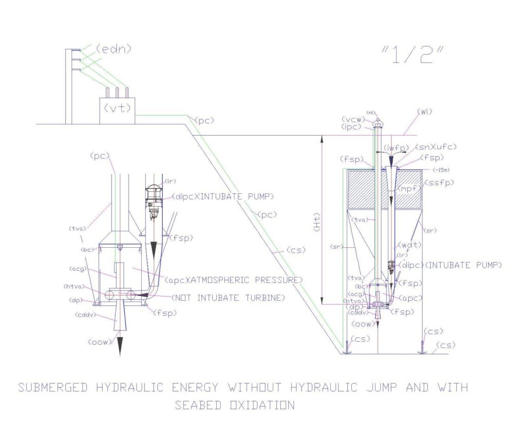
The drawing. “1/2” fig. 1 shows schematically the system with radial flow turbines with vertical axis. From the top, you can see the floating structure (mfp-ssfp) subjected to sea level of 15m; the descent tube of the water that carries the axial submersible electric pump with the suction upwards; the reduction in section and the curve that connect to the turbine, which drains the water from the bottom through the diffuser cone (cddw). The turbine (htva) is contained in a steel chamber at atmospheric pressure (apc), with a small bridge crane for possible maintenance operations. In this solution the turbine remains incorporated in the chamber, any repair and replacement of worn parts must be made on the site, while there is the possibility of extracting the alternator through ventilator tube and access (tva), after disassembling of the terminal element (vcw) which serves to keep out rain water and high waves that will exceed even the terminal element. Inside the room, however, is expected to pump lifting water and condensate level control (dp). On the terminal (vcv) is mounted night lamp (nl) to indicate the presence of the plant. You may notice the electrical wiring path (pc), the central energy conversion (vt) and the distribution network (edn).
The fig. 2 is an enlargement he lower part of the system described above.
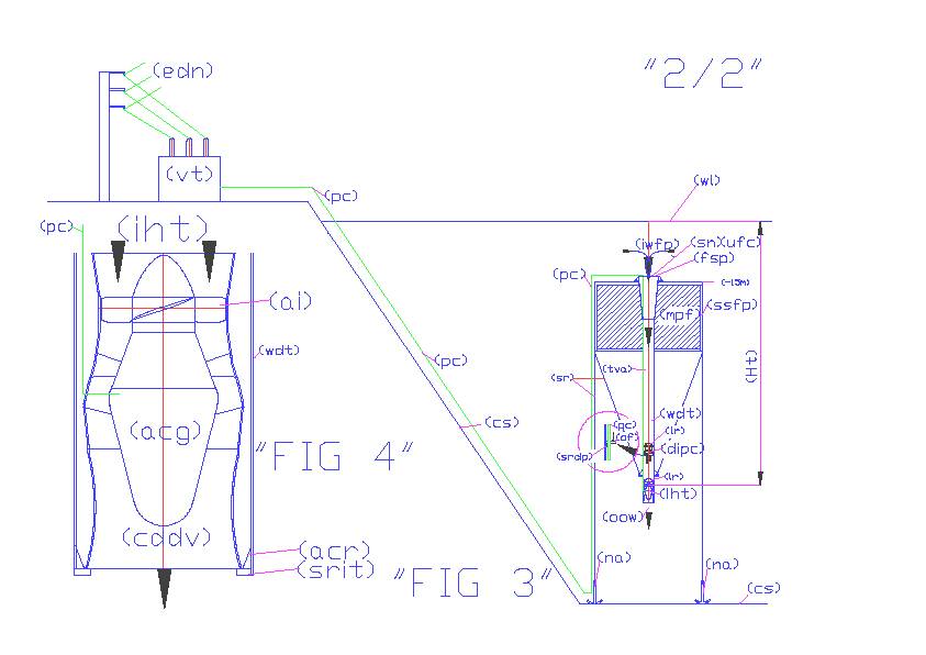
The drawing “2/2” fig. 3 report schematically the system with intubate turbine. This solution has been designed to provide not surface in any area exposed to storm surges. It is ‘the ideal solution. But, currently, these turbines are installed at a maximum depth of 15 m. Manufacturers will have to improve the mechanical seals of submerged parts that protect the electrical components and the lubrication system, if you want to install the turbines at depths of 50 m and beyond. It can be noted that the plant with this solution is much more simple and economical. In fact, in the same descent tube water (wdt) is mounted before the pump (dipc) and subsequently also the turbine (iht). In fact, as can be seen from the detail circled the pump will be equipped with a Oversized Flange (of) that rests on the support ring (srdp); cables pass through the flange of the pump power and also the power cables (pc) alternator (acg) of the turbine, which rests on the ring end (srit) driven by self-centering ribs (acr). Obviously, the electrical cables must be protected in metal pipes and to bring out the turbine must first remove the pump. You may notice the electrical wiring path (pc), the central energy conversion (vt) and the distribution network (edn). The fig. 4 is the enlargmentof turbine (iht) and of the support system in the tube (wdt).
Luigi Antonio Pezone