The sustainable future of environment, energy, food and labour is based on the new hydrology.
(Technology in service of man and environment without hypocrisy)
Abstract
This publication is the presentation of the latest patents deposits of SPAWHE (Synergic Plants – Hydro (compressed) Electromagnetism – Artificial Welling), that is not a corporation, although could have been more powerful than Microsoft, if sustainable development were a real objective for the men of power. Instead, SPAWHE is the website of a pensioner without a dollar of capital. The latter patent applications dealing with desalination, power and sustainable energy and are connected to the previous project, that nobody has funded and implemented, which have had a virtual development in the inventor’s mind, without which, these desalination, food production and energies can never be realized.
The sustainable future of the environment, energy, power and labor is not in the direction in which we are going for the simple reason that the worlds environmental and energy lacking “the scientific organization of work” that has led to the current industrial and economic development. The big problem of global warming, but also that of migrants, unemployment and hunger in the world should give pause to the designers of the production facilities of consumer goods, environment, energy, urban areas, agriculture, to try the most comprehensive solutions, drawing on everything that we have available in the various scientific and technological disciplines. These serious problems cannot be left only in the hands of politicians, economists, and multinationals, who, for various reasons, are not able to get technical solutions that are able to create a sustainable and durable prosperity. Politicians are not technicians, while economists and multinationals are interested in the application of scientific work only from the point of view of economic growth based on productivity of consumer goods and the money exchange. Today economists, multinational corporations, and manufacturers of consumer goods are the only ones who know and apply the scientific organization of labor, theorized in 1911 by Frederick Taylor. This discipline has been more helpful than thousands of inventions, having allowed multiplying the production capacity of the plants with respect to quality. In 2016, given the great results achieved, we must ask ourselves why were not spent the same energy to organize scientifically, at global level even environmental protection? SPAWHE, lacking funding, has applied virtually the scientific organization of work also to the environment and to energy production, using rationally the developed industrial technologies.
Keywords: spawhe, vertical desalinators, ion exchange, hydroelectric energy, dual supply pump, floating system, calcium, carbon, marine water, food, global, organization.
Introduction
The way of working in the environmental and energy sector has created many individual and corporate professionalism super specialized in individual areas but lack the professionalism able to put them together properly on the territory to achieve a common objective, as happens in the manufacturing industry, where all departments are connected with precise working cycles in order to obtain the productivity and quality of farm products. If we consider the planet Earth as a great producer of consumer goods to sell and market, we would find that in the environmental sector – energy, there is almost nothing in common between a department and the other departments and which are connected using transport systems which affect the quality and productivity of the final product. Even today, if do not intervene rains and winds, not to purify the pollution, but for dispersion in the environment, turning it into global pollution, urban life would be impossible. But we can not be satisfied with this solution and even of monothematic competition announcements organized by international environmental authorities such as the following http://ec.europa.eu/research/horizonprize/index.cfm?prize=clean-air postponing the solution of the problem in an open competition to be submitted by January 2018, while in the meantime, the same Europe that has launched this competition, left to decay many international multidisciplinary patents of 2012, published on http://www.spawe.eu. No served three open letters published on the website and sent to several members of the European Commission. The bureaucracy is unable to respond to the concrete proposals that arise from experience, must do their own course and their victims, of which no one is guilty. No one realizes that in the public sector the right hand does not know what the left is doing, while the private sector is developed independently, without taking into account the global problems. The Principles of Scientific Management never entered in the environmental and energy aspects. If it had entered, the plants would not be randomly placed on the territory, the chimneys would be eliminated, the sewers would become purifying water and air together; the hydraulic lifts for water distribution and defense of the territory would have circumvented the strength to gravity, instead of wasting energy to win. The greatest fault of the current environmental degradation is of the public authorities that have accepted the onerous task of defending the environment without having the humility to copy organizational ideas of labor from other sectors. After more than one hundred years the advent of the industrial Taylorism, there is not yet the slightest semblance of an environmental Taylorism. Environmental activities proceed in random order in the depuration and in energy production. Resist, especially, the smokestacks and sewers that were to be the first things to change when the world has begun to talk about global warming. What does it take to understand that water and air are not amorphous substances, but lives and reagents, from a chemical and biological point of view. The polluted water to be treated, can not expect to reach the distant purifiers and the polluted air can not simply be filtered, since the combustion cycles do not end at the exit of the chimneys but also when the exhaust gases were neutralized, including CO2. Does not make sense in 2016 have water purifiers far from cities, not purifying urban air and have millions of air conditioners, which exchange air-air heat in the summer months, when we could, with the available technologies, have purifying sewage of water and air, exchanging heat with the subsoil, These should have been the first things to do for proper environmental management. The industrial Taylorism is based on precise work cycles, according to which, are designed the machines, the equipment that serve and the transport means for connecting the processing departments and mounting. Nothing is left to the case, except the environmental aspects, which adjust to the low overall quality.
In scientific organization of the world’s environmental work does not make sense do not try to exploit the immense ocean space to create supplementary feeding, raising the carbon and the dissolved calcium from the high hydrostatic pressures, fighting in this way also ocean acidification. Does not make sense to waste energy to lift the water, without first trying to get around the force of gravity by means of the dual fuel pumps from the suction side. Does not make sense to produce thermal energy, solar, wind with very low yields and not take advantage of the hydrostatic pressure on the pumps combined with the turbines on always-filled basins, knowing that the hydrostatic pressure at the outlet of the turbine is not opposed to small residual kinetic energy. Does not make sense to exploit the batteries of lead accumulators and with acids to produce mobile power and not try before to use compressed air as an energy accumulator, certainly more environmentally friendly, especially if combined with hydropower.
Everything that did not provide the international scientific community is expected to SPAWHE, without a single dollar or euro financing. Authorities Environment and Energy pretend not to understand and continue, for them, the road to banish purifying and energy monothematic competitions, regardless of collected failures against global warming, before and after the Kyoto Protocol. Who decided that public facilities are to produce services, purifications, desalination, energy with unsustainable costs charged to taxpayers? It is obvious that you can not hire workers if the work is unproductive and uneconomic. With the global scientific organization of work public systems regarding these sectors will be able to multiply the efficiency and productivity, producing economic prosperity that serves the imminent growth of the world population. Go on pretending that global proposals SPAWHE not exist, it does not help the overall growth of the economy and environment protection. The world’s leading authorities environment and the economy, if not make the first step, by funding the global systems of SPAWHE and issuing regulations governing proper environmental planning, can not pretend that it is the market and the search for partners among professionals private works, specialized in individual areas, especially trade, to incorporate issues that go far beyond the task of entrepreneurs. It is obvious that the insiders private works oppose silences interested. Why should produce pumps with dual suply on the suction side to get around the force of gravity when the public market does not require them? And what about the science that teaches how to correctly calculate the flow resistance and the absorbed power in the wrong hydraulic systems from the energy point of view? Even science, like all professionals, has many reasons to remain silent on the proposals of Spawhe. The scientific organization of work applied to the environment, energy, sustainable and oceanic colonization desalination described SPAWHE is much more complex than that theorized by Taylor in 1911.
We see in detail the latest news of SPAWHE, in addition to those already published. Every plant engineering solution is described in a chapter composed of a summary, a description, and the necessary drawings.
Chapter 1
by Italian patent demand No. 102016000057968 of 07.06.2016
VERTICAL DESALINATORS – DEMINERALIZERS BY ION EXCHANGE WITH HYDROELECTRIC ENERGY PRODUCTION
Abstract
The state of the art in the development of desalination and demineralization treatment of marine and brackish water has been conditioned, as many other industrial systems, depuration, energy and protective of the environment, by the absence of synergies between the pumps and hydraulic turbines and from the incorrect approach to the gravitational force, which is not to be won by lifting hydraulic but sustained, with a one-way circulation of water in open reservoirs, upper seats that double as hydraulic backflow preventers. With the triple synergy between the dual supply pumps, turbines and recycling of water in an open vessel, applying hydraulic principles known for centuries, such as the principle of communicating vessels, the laws of Bernoulli and Pascal, strategically placing the electric double suction pumps between a high positive hydraulic head and the turbines, dimensioned for the exploitation of the same hydraulic load, the pumps, working with a balanced load, with a small energy consumption, they win the state of inertia, allowing the energy transformation of pressure of the intubate water column overlying the pump, into kinetic energy and transferring it to the turbines, which produce energy. These spheres, floating climbing ion exchanger and descend by gravity, emptying water in downhill tubes. By means of diverters change the path compared to the flow to be immersed in the washing tanks and regeneration of the resins, and reinserted again, indefinitely, in ion exchange circuit without interruption of the desalination cycle and energy production and without costs for heating the water or replace the membranes. The demineralized water serving for the washing of the resins is produced by continuing the process through a mini system completely similar to the main that part from the desalinated water tank. If men want to produce desalinated water in industrial quantities that serve humanity, also desalination plants, as purifiers and water lifting and distribution, must become producers of energy, not consumers, supporting, not opposing gravitational forces. The sustainability of global systems is not based on complicated technology but on synergies between simple and rational systems.
Description
In the present state of the technique of desalination and demineralization are headed three types of installations: by evaporation, permeation through membranes, for ion exchange. Currently, the difference between the three systems, mentioned above, makes it especially the cost of treatment. That evaporative, produces water free of mineral salts and with acid pH, therefore for the use of water is required a subsequent mineralization and neutralization of the pH.
The filtration with membranes entails high operating pressures, therefore high energy consumption and the high cost of the membranes, which periodically must be replaced.
The one with the ion exchange resins involve a complex filtration, washing and regeneration circuit of the resin, with reverse flows that involves the dispersion of apart of the resins in waste waters of the processes.
All processes are heavy on energy consumption for heating or for circulating pressurized water in filtration and regeneration systems. The operating costs are around 1.5 euro / mc with reverse osmosis plants, which are the most used, but also the investment costs are significant, being about 1000 Euros per m3 / day of desalinated water produced. It ‘obvious that with these production and investment costs, the desalinated water can be used only for potable use. It ‘s impossible to think to use it for industry and agriculture. With the solution that proposes the agricultural and industrial use will become a competitive reality also with wells and other purification systems, which are in any case forced to treat polluted water, or with scarce mineral requirements. In fact, the sea water being rich in mineral salts, If desalination becomes sustainable, can become the best natural fertilizer for land, being able to send the same water can be used as fertilizer treated tailored to the target terrain, both in terms of mineral salts that alkalinity. For transport the desalinated water to considerable distance there is no problem, because with the dual supply pumps coupled to the hydraulic turbines, also the transport and the lifting of the water becomes a source of energy, not of consumption. In fact, the key to solving many environmental and energy problems, including desalination, is to realize Hydraulic and hydroelectric circuits using otherwise the pumps and turbines.
At the state of the art the desalination system least used is the one with the ion exchange, but this system is the most suitable to be used in conjunction with the dual supply pumps and turbines, not having the necessity of high temperatures or high operating pressures than competing systems. Therefore, the high cost of the resins and of the reagents liquid, required for regeneration, can be largely compensated by low energy consumption, energy production produced by the plant and low cost required for plant, and low operating and maintenance costs. Furthermore, with the solution described below, it will also solved the problem of the dispersion of the resins in water and process liquids, being the resins contained and circulating (in water and chemical reagents) in perforated polyethylene spheres with holes pass below the size of the same. We can say, that the new solution is opposite to the current of ion exchange solutions, where the resins are stopped and the liquid passes through them, both in the reaction phase than in those of washing and regeneration. With the system proposed resins are circulating in the water and in the regenerating liquid, at low speeds, with long contact times, which provide capillaries contacts. For the circulation exploit physical principles, not energy. Over 90% of energy produced in the plant can be transferred to public power networks. Therefore, the facility is composed of a chemical part, an electromechanical and a hydraulic.
The chemistry of ion exchange.
From the scientific literature, one can learn that the ion exchange, is a process in which ions of a given species are replaced on the surface of a non-soluble material exchange (ion exchange resin) by ions of a different species dissolved in solution. It consists of two phases: cationic and anionic. In the proposed plant, which develops vertically, these stages take place separately in large diameter pipes (5) making transit at low speed an appropriate quantity of balls in polyethylene perforated like a sieve, containing granules of anionic resins or cationic in quantity proportional to salts to absorb, selected with a diameter greater than the passage of holes. The ion exchange resins can be natural or synthetic.
The natural resins are zeolites (aluminosilicates) used especially for the softening of the water and for the removal of ammonium ion.
The synthetic resins are formed from phenolic polymers which are generally in the form of small spheres of a diameter between 0.3 and 1.3 mm. With a density of 1.2-1.3 kg / l. They can be of two types:
a) cell structure: translucent, low elasticity, higher capacity;
b) macroporous structure: matt, high porosity, lower capacity;
the basic structure of the two types is however identical both being obtained by copolymerization. The realization of synthetic resins is generally through a process of copolymerization between styrene and divinylbenzene. Styrene has the resin matrix function, while the divinylbenzene serves to give consistency to the resin. The main properties of ion exchange resins are:
– the exchange capacity is expressed in meq / L or eq / kg. It is defined as the amount of an ion exchange resin that can lead.
– The size of the resin spheres: the importance of the dimension lies in the fact that the kinetics, and the rate of ion exchange columns is a function of the same. In general the rate of ion exchange is inversely proportional to the square of the particle diameter.
The ability of stated exchange of a resin varies according to the type and the concentration of substance used to regenerate the resin. Generally, the exchange capacity of a synthetic resin varies between 2 and 10 eq / Kg resin, while the zeolites have a cationic exchange capacity ranging 0.05 to 0.1 eq / kg resin.
Often the exchange capacity of the resins is expressed in terms of grams of CaCO3 per m3 of resin (g / m3) or equivalent grams per m3 (g eq / m3).
The level regenerative: is the quantity of regenerant (HCl, H2SO4, NaOH) considered at 100% required to regenerate a liter of resin. It is expressed in grams per liter of resin regenerant.
The total capacity of exchange: It is the concentration of active sites per unit of measure. It is for unit of volume (Eq / liter) or weight (Eq / g) and is a parameter specified in the data sheets of the resins.
The operational capacity of exchange: is the quantity of ions (Eq / liter or g CaCO3 / liter) that a given exchange resin under specific working conditions in which it is used.
The process schemes vary depending on the objective of the treatment to be carried out.
Some classic treatment achievable with the ion exchange resins are: softening, decarbonation (partial demineralisation) Full demineralization, removal of heavy metals specify, but substantially, ion exchange, such as ultra filtration, if it becomes sustainable and energy is also a great third party purification system.
As initially said the ion exchange generally involves the exchange of an ion present on the functional group of the resin with an ion of the same charge present in solution.
At the state of the art are distinguished five types of synthetic ion-exchange resins:
1) strong cationic resins, 2) weak cationic resins, 3) strong anionic resins, 4) weak anionic resins, 5) chelating selective resins for heavy metals.
– The strong cationic resins behave in a manner similar to a strong acid and are highly ionized in both their acid form (R-SO3H) that in that saline (RSO3Na) in a wide range of pH values.
– The weak cation resins have a weak acid functional group, typically a carboxyl group (COOH). These resins behave as weak acids, and as such have a low degree of dissociation.
– The strong anionic resins are strongly ionized due to strong basic groups such as the hydroxyl anion (OH) and may be used throughout the pH range. Thanks to the hydroxyl OH group are often used for the deionization of the water.
– The weak anionic resins are carriers of the weak basic groups and therefore have a degree of ionization depends on the pH, generally ionize in narrow pH fields.
The selective chelating resins for heavy metals behave as strong cationic resins, however, presenting a high degree of selection in the ability to chelate heavy metal cations.
Note that the ion exchange reactions are real equilibrium chemical reactions and as such reversible. In this regard, the working cycle of a resin is composed of two stages: – the operating phase also called “exhaustion” during which the reactions go from left to right (that is, it has the replacement of the ions present on functional groups with those present in the solution) and that end with the saturation of all functional groups. This phase, in the plant in question, takes place in the ion-exchange tubes (5).
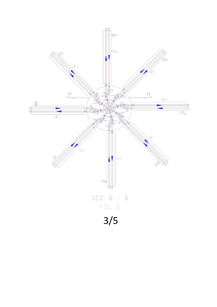
– The step of charging also called “regeneration” in which the reaction is allowed to proceed from right to left by reloading the functional groups with originating ions of the resin. In the proposed solution, the regeneration takes place by passing the polyethylene perforated spheres, with the incorporated resin, in tunnels immersion of regenerating liquid and washing (E), consisting of:
– Basic solutions, typically basic substances type NaOH, NH4OH, in the case of anionic resins. In that case, recharge the resins with OH- ions.
-Solutions acidic, typically based on strong acids (HCl, H2SO4) in the case of cationic resins. In this case recharge resins with H + ions.
The high concentration of H + ions and OH-, in the two cases causes, for the law of mass action, the displacement of the reaction to the left resulting in charging of the resins and release of the ions in solution which in the exhaustion phase (5) were It has been absorbed by the resins. This obtains an eluate generally composed of various metals chlorides (if using HCl, the H + ion charging the resin, while the Cl- ion binds to the cation released from the resin) or the various salts of sodium in the case of using NaOH ( the ion OH- charging the resin, while at the Na + ion binds to the anions released in regeneration from the resin to give sodium salts).
ES.: Ca++ + 2HCl → CaCl2 + 2 H+; SO4— + 2NaOH → Na2SO4 + 2OH.
The ion exchange resins for the fact that exchange hydrogen ions (cationic) and idrossilioni (anionic) are more properly defined cationic resins in acid cycle (RH) and anion resins in the basic cycle (R-OH), owing to the characteristics of the released ions which make the acidic or basic water.
Below are some of the ion exchange reactions for synthetic resins:
Strong cationic resin:
R-SO3H + Na+↔ R-SO3Na + H+; 2R- SO3Na + Ca2+ ↔ (R-SO3)2Ca + 2Na+.
Weak cationic resins:
R-COOH + Na+ ↔ R-COONa + H+; 2R-COONa + Ca2+ ↔ (RCOO)2Ca + 2Na+
Strong anionic resin:
RR’3NOH + Cl–↔ RR’NCl + OH–.
Weak anionic resin:
RNH3OH + Cl– ↔ RNH3Cl + OH–; 2RNH3Cl + SO42-↔ (RNH3)2SO4 + 2Cl–.
Example of exchange and regeneration.
Removal of sodium ions (Na +) and calcium (Ca2 +) from water using a strong cationic resin. Reaction: R- H+ +Na+→ R -Na+ +H+; 2R– Na+ + Ca2+ → R2–Ca2+ + 2Na+
Regeneration:
the regeneration is carried out with hydrochloric acid (HCl) and sodium chloride (NaCl)
R–Na+ + HCl → R–H+ + NaCl; R2–Ca2+ + 2NaCl → 2R–Na+ + CaCl2.
The selectivity of a resin, namely the fact that an ion present in solution in active sites, exchange with those rather than another, depends on the nature and valence of the ion, the type of resin, by its saturation, as well as by the concentration of one specific ion in solution. Generally such selectivity remains valid in a narrow pH range. Typically the selectivity scale or if we want to affinity of the cationic resin exchange turns out to be:
Li+ < H+ < Na+ < NH4+ < K + < Rb+ Ag+ Mg2+ < Zn2+ < Co2+ < Cu2+ < Ca2+ < Sr2+ < Ba2+ ; while for the anionic resins it is: OH– <<< F–< HCO– < Cl– < Br– < NO3– < ClO4–
In current of ion exchange systems the operating phase provides, generally, the passage of water in a resin tank filled and a flow rate of water that must be kept within certain limits to ensure adequate exchange times. The characteristic data are highly variable in function of the amount of salts and ph: operating flow rate of between 5 and 50 liters / h / liter resin. It ‘very difficult to manage and control the complete process, especially if you need to desalinate large flow of water. Even the regenerative phase, currently, it is not easy to handle. It is divided into three sub-phases.
a) Washing in countercurrent (backwash): water in upward flow, the flow velocity equal to 10-15 m / h, 50-70% of the expansion of the resin bed. This washing serves to eliminate any preferential paths formed during the exchange phase and to remove impurities that may have possibly formed in the bed during the exchange phase. The duration of this phase, in existing plants, is around 15 minutes.
b) The regeneration can be acidic or basic depending which relates to a cation exchange resin or anion respectively. The solutions are dilute solutions of acid or base whose percent dissolved depends on the strength (degree of dissociation) of the same. For example, to recharge a cationic resin can be used acidic solutions such as:
5 – 10 % di HCl with flow of 3 -4 l/h/l of resin.
1 – 3 % di H2SO4 with flow of 10 – 15 l/h/l of resin.
c) Final washing which is carried out with demineralized water in a down flow in two phases:
a first phase to the flow of the regenerative phase to wash the residual acid;
a second phase to the operating conditions for a total volume of water equal to 6 – 9 volumes of resin.
The new electro-mechanical and hydraulic systems of ion exchange.
The long introduction, above, who summarized the state of the art of chemical and physical processes that govern the complex ion exchange system is essential to understand the reasons why it is born this invention. In fact, the work cycles of the current systems that use the ion exchange are the starting point for the design of these new plants, which must not distort the basic principles, but should only make them cheaper, especially, by combining the production of energy hydroelectric, low cost, that sold to operators, of fact, lowers the cost of desalination. In fact, hydropower produced without the classical hydraulic jump, is much cheaper than the current hydropower, not requiring the construction of dams and reservoirs. Just only the utilization of positional energy of water placed in the high position of a water system remained always full to take advantage of favorable hydraulic condition for energy purposes. Therefore, the plants, with ion exchange, combined with the production of energy, in addition to the desalination and demineralization, may also have other cleansing applications, so that even the sweet water, in many cases, even when they are extracted from the subsoil, must be deprived of undesired substances because of the numerous infiltration due to the chemicals used in agriculture, in industry, in urban activities, infiltration of solvents and radioactive metals freed near drilling with the system of fracturing water with solvents and inert materials at high pressure. Certainly, even the ultra filtration can be combined with the production of hydroelectric energy, reducing operating costs, but most of the energy would be consumed in the same facility, while the cost for the replacement of worn membranes would not be solved. In addition, it is necessary to clarify that state of the art, not desalination sea water but only brackish waters because desalination the sea water would cost about 3.5 times the current costs, which already are not sustainable for large jobs ladder. In fact, in the process for reverse osmosis, the water by desalination is put in communication with fresh water through a membrane permeable only to the solvent; applying on the side of the saline solution a pressure higher than that which is generated by osmosis, it reverses the normal direction of spread and the solvent tends to leave the solution with higher content of salts. The process is not yet used for the desalination of sea water, since, being the osmotic pressure between sea water (salinity medium: 35 g / l) and distilled water equal to approximately 22 bar, the corresponding pressure required to obtain a appreciable flow of solvent through the membrane may even exceed 100 bar. The process is, instead, application for the desalination of brackish water with a salinity less than 10 g / l. In the same proportion they will also increase the energy costs of evaporative processes, while with the ion exchange proposed only increases the cost of the chemical additives and of the amounts of resins required.
Before starting the description of the process should bring the legends of the figures illustrating the plant.
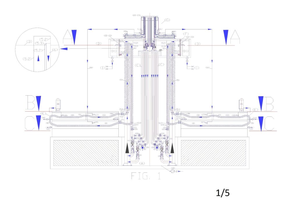
Alphabetic legend: (A) arrival basin of salted water; (B) salt water inlet filter with built-in check valve; (C) Water recirculation tube and dynamic or kinetic pressurization of the electric pump; (D) Nominal upper basin level; (E) washing and regeneration circuit of ion exchange resins; (F) upper reservoir mixing and overflow desalinated water; (G) Mini implant of deionized water production; (H) desalinated water storage basin; (I) desalinated water distribution network; (L) demineralized water accumulation tank; (M) regenerating liquid tank.
Numerical legend: (1) overturned dual supply pump on the suction side; (2) submerged turbine with incorporated alternator; (3) nominal level of the water basin to desalinate; (4) pipe for supplying water to desalinate; (4.1) special piece for introduction spheres with resins in the ion-exchange tube (drilled in the lower part); (5) tube of ion exchange; (5.1) perforated truncated cone embedded in the tube 5; (5.2) special piece to eject spheres from the tube 5 (perforated on the entire outer surface and connected to the tube 6 by means of the slide 5.3); (5.3) metal sheet slide for the guidance of the spheres in the tube 6; (6) tube of descent spheres for the emptying; (6.1) special piece for the deviation of the spheres from the ion exchange circuit to the regeneration circuit (drilled at the bottom for water drainage); (7) automated guillotine valves for stopping movement spheres (are always open when the minimum level probe indicates that the tube 6 is empty of water; (7.1) automated guillotine valves for stopping movement spheres (open one at a time); (8) first tunnel for immersion wash of the resins; (9) guided route of the spheres in the immersion tunnel with an open frame of stainless steel rods by ascents and descents with slides for the collection of the of the spheres emptying liquid; (10) tunnels for regeneration of the resins in immersion; (11second washing immersion tunnel of the resins; (12) pump suction sludge from arrival reservoir; (13) electric pump suction of resin washing sludge; (14) electric pump suction of resins regeneration sludge; (15) Support frame demineralisation plant; (16) supply pipe demineralized water; (17) float valve for feeding demineralized water; (18) float valve for regenerating liquid supply; (19) motorized shut-off valve; (20) Manual shut-off valve; (21) check valve; (22) salinity control probe; (23) PH control probe. (24) minimum water level control probe of spheres emptying tube; (25) submerged agitator.
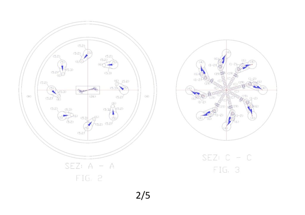
Figure “1” shows the general scheme of the plant in a vertical, where you can see in section the elements reported in the legends, while Figures 2, 3, 4, report the sections to altimetric plans A, B, C.
Annotations on hydraulic principles and fluid used.
So that it produces the maximum energy kinetic energy in a pump-turbine group, place under a head, which discharges the water in depth, within the same basin, it is necessary that the water is drawn from the highest point of the ‘ plant and arrives directly on the pump placed in the lowest point of the system. In fact, it is known that a moving body (including water), increases its force (F = m * a), both if it moves horizontally or vertically. Obviously, in the case of water, if it moves in the horizontal acceleration must provide all the pump motor, if it moves vertically, in the direction of the gravitational force, to the acceleration provided by the pump, it also adds the acceleration gravitational (g = 9,81 m/s2But it is not sufficient only to orient the pump downwards and exploit the hydrostatic head, because the mass of water that would move without the vertical intubation, would be only that is around the pump, therefore, the turbine would produce very little energy. The surface water intubation is essential to provide the entire water column above the pump energy of movement. Therefore, it is necessary to use a descent tube (c) for each pump-turbine group. On the other hand, this need is intuitive, since even the turbines that exploit the hydraulic jump to the atmospheric pressure are connected individually to the upper reservoir. Contrary to what one might think is not the flow rate combined with pressure drop to produce in traditional hydroelectric energy, but the flow of water transformed into kinetic energy (or dynamic) realized in the path that feeds the turbine (P = η*1000*Q*Hu/102).
In traditional hydroelectric energy it is not commit calculation errors because flowing the water to atmospheric pressure and not recycling it, the whole static pressure energy, reclaimed from the load losses, is transformed into kinetic energy. But the traditional hydropower should have been the exception that proves the rule, however, for the experts, it has become the rule, and no one wants to deepen the utilization of surface energy of water location within the same volume of water, which can be done anywhere without building dams and large hydraulic basins. In fact, in the case of installations always filled with water, not having, a hydraulic jump to exploit, to produce kinetic energy is necessary to take advantage of the relative position difference within the same volume of water, thus the plants and the pumps must be designed otherwise. It ‘necessary to intubate the surface water to take advantage of his energy of position with respect to the pump location and the turbine, which connected in series, function as one single machine: the pump wins the state of inertia and keep the motion in time allowing the acceleration of gravity to produce more kinetic energy than it spends the pump, while the turbine uses the total energy to produce electricity through the built-in or connected alternator. It ‘obvious that if only ponessimo the ducted pump under a swing of 10 or 20 m of water column, there being no hydraulic resistance in the flow, it would create a large hydraulic imbalance, since all the kinetic energy developed by the water column , due to the acceleration of gravity on the pump, finding no contrast, apart the friction of the water molecules, it would be dispersed into heat. In fact, the static pressure of water, to the fact that the liquid is incompressible does not oppose to the kinetic energy. Therefore, the velocity would increase in the permitted limits and the pump would be damaged in a short time, failing to control the flow of water that it would have started. Insert a turbine after the pump, in addition to being a rational energy solution is also the balancing element of the forces generated. Therefore, with the proposed system we can produce energy in the turbine by the energetic flywheel constituted by the masses in movement in the direction of gravitational force, discharging the water in the open basin, or in an open section connected to the upper reservoir, with small residual velocity at the exit of the turbine. The load loss to be calculated for this discharge is more or less the same that would have with the discharge tof he water in the atmosphere (V2/2g). It is ‘equally obvious that without the water intubation that part from the surface we could not produce the kinetic energy that is used to produce electricity, since the water that would power the pump would be surrounding the pump, equipped with only one static pressure. These are the reasons why in the diagram of Fig. 1 each pump is connected with a suction mouth to the upper reservoir and for which this tube has been called dynamic pressurization tube. In fact, the static pressure in a closed circuit can be transmitted with a small tube (Just think of the famous experiment of Pascal that with tube full of water placed vertically, smashes a wooden barrel), while in order to give at a flow rate of the water pressure dynamic (or kinetic), it is necessary that the unitary pressure is multiplied by the water passage section (10 m column of water equivalent to 1 kg / cm2). If we have a passage section of 100 cm2 and we want transmit dynamically the entire pressure of the ten meters of water column, this section must be maintained and extended considering the load losses for not to lose kinetic energy. This must cover the entire circuit path, including the body of the pump. So if we want a dual supply pump sends water fed from the lower basin (always with a positive swing) the dynamic energy of the water coming from the reservoir (F), the passage in the pump sections must be adapted to the sum of the two flows. In such conditions, at the pump outlet we will have a single flow and a single pressure, which will approach the sum of the flow rate and the maximum inlet pressure, plus that provided by the pump, minus the pressure losses of the circuit. This application is also confirmed in Torricelli’s theory that showed that the output speed of the water to a hole made on the wall of a water tank under a hydraulic head (h) is calculated with the formula √2 * g * h, regardless of the actual depth of the tank. Obviously, this confirmation should be interpreted only as the certification of existence of surface water energy location. But to harness that energy for electricity generation in the same volume of water or in plants always full, recycling water, is necessary modifications to the pumps and hydraulic circuits currently used, since at the current state of the art, no one has done the right technical and scientific reflections. The same patent offices, in previous applications of the undersigned, have declared such applications contrary to the principles on energy conservation, not distinguishing the difference between simple and complex circuits. In fact, the hydraulic principles of the Energy Conservation legislated do not include complex hydraulic circuits made within the same volume of water, which can feed endlessly internal circuits, considering the basin always full, therefore, respecting the principles legislated. With the surface water intubation and the coupling under the head of the pumps with the turbines, of fact, are realized within the same volume of water many hydraulic systems separate from the static water, as there are pump-turbine groups realized. Each group produces electricity, by the difference between the energy consumption and spending, independently from the other groups, drawing on common energy source, which are the energy of surface water location and atmospheric pressure. The system can also produce energy by lifting water from a basin to another as long as the circuit is always full and the water to be lifted is inserted into the recycling circuit of upper reservoir by means of a feeding of a pump with double mouth placed under the head, dynamically pressurized by hydrostatic height of the upper basin on the second suction inlet.
Obviously, in a basin always full, even the static pressure is dispersed. These considerations do not need to be demonstrated with prototypes because if they were true, they would not hesitate sea currents and underwater pipelines may not discharge the water in the deep seabed with small kinetic energies. If this happens it is precisely because the exhaust pipe part of the surface, the internal static pressure and external to the tube are balanced, while the energy developed inside the tube with the insertion of the pump under the hydrostatic pressure contained in the same tube, communicating with the upper reservoir and with the atmosphere, finds no opposition, apart from the famous V2/2g.
Another authoritative confirmation comes from the famous scientist Albert Einstein, who with his theories of relativity showed that matter and energy can be considered as a unit, since the one can become the other according to a precise mathematical relationship. A practical confirmation of this statement we can find in the action of the wind can generate electricity through wind turbines but can also break the inertial balance between the troposphere and hydrosphere, creating kinetic energy in ocean currents. This, for myself, is the energy aspect underrated in the world, because even we can break this balance, artificially, by means of intubation of a small stream of water, a pump placed in the depth of the water and concentrate all ‘kinetic energy produced on the blades of a hydraulic turbine. There is no law of conservation of energy that can prevent it and no energy balance to do, except that between the energy used and that produced, because we take energy from an endless source. The difference between expenditure and energy produced is immense, in favor of the energy produced, because we are not in an isolated system as the pendulum of Newton. In fact, all the weight of the water column intubated (m * g * h) gains kinetic energy (1/2 mv2) braked by the blades of the turbine, which produces electricity by alternator connected, under the weight of the water masses conveyed on the turbine to the effect of gravity and atmospheric pressure, once moved the masses of water below by means of the pump. In fact, Einstein says that the energy provided it does not increase the speed of the body, but its mass: the body becomes more and more “heavy”. This is also reflected in the practical calculations of the prevalence of lift pumps which is subtracted from the positive head on the suction side, being considered an energy in all respects. This energy becomes even more important if instead of raising the water we use pumps to produce energy. In this case, it is convenient that pumps orient the flow of the flow in the direction of the force of gravity and atmospheric pressure. Using this system the difference between the energy used and that produced becomes huge because the surface water has the same density as water below, and therefore does not need to rise to the surface, if we are in a small basin (The water simply changes position). The energy production is huge, as realized in terrestrial hydroelectric, at atmospheric pressure, because the exit of the turbine the hydrostatic water pressure cannot oppose the kinetic energy remaining. In fact, because water is incompressible, at any depth is on the outlet, the hydraulic resistance to the output is always the same (v2 / 2g). Therefore, energy expenditure may be multiplied by a hundred, two hundred, etc. It depends only on the water column, which weighs on the pump and on the turbine.
The dual supply pumps on the suction side (italian demand patent N. 102015000048796 del 04/09/2015).
The dual supply pumps on the suction side, used in this system do not exist, as described above, for the wrong interpretation of the fluid dynamic principles, which have resulted in enormous waste in all areas of human activity, but are simple to realize by changing the supply of current pumps, not the construction technology of the same. In fact, by feeding the impeller from the outside by two confluences (curves or grafts with different angle) channeled internally, so that the two flows cross each other and nourish the pump impeller into four separate sectors, arranged diagonally, two fed with ‘ water to be lifted and two fed with the recycled water from the top, equipped with high hydrostatic pressure. Balancing in the above manner the hydraulic thrust on the impeller and on the bearings, and by getting its flows deep into the impeller, so that they are not in contact before being dragged by the impeller itself can transform all existing hydraulic systems from energy absorbers to producers of the same, of course, also modifying plants and inserting the turbines in series to the pumps.
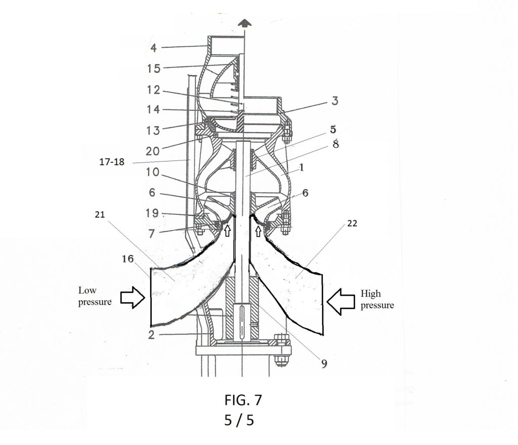
We start from the heart of a pump that is the impeller, which can produce an axial flow, radial or axial seeds and can be opened, closed or semi-closed, in function of the pump body in which is mounted. There are also pumps with twin impeller, with horizontal shafts and double feed at the same pressure, which have excellent performance, but we do not take them into account, since the pumps that we propose, to simultaneously take advantage of the hydraulic principles of communicating vessels and Pascal, who allow increments of flow rates and low energy cost pressures, they must be supplied with different hydrostatic pressures. All pumps can be changed and fed with different pressures. Obviously, with different performance and returns in function of the characteristics of the impellers that are currently mounted. With high flow and small increments of pressure will be used axial or half axial impellers, with small flow and more pressure will be used closed impellers and more precision of the workmanship, as happens in the current pumps. The important is to understand that these pumps should never work in suction but only under the head and that dividend flow which reaches into four sectors that arrive directly at the entrance of the impeller, with the rotation of the pump, in each sector is alternated l ‘ entry of water into high and low pressure, which have the same direction, therefore the flow rate with greater pressure transmits its pressure to the flow with lower pressure inside the same impeller, which as is known is designed to increase the water pressure starting from the center to the periphery of the rotor itself. Obviously, at the pump outlet we will have only a single stream with the sum of the flow and the greater pressure. This is nothing but the dynamic application of the principle of Pascal, that with current technology it is simple to implement. Figure 6 shows the change of a pump with axial impeller, Figure 7, that of a pump with closed impeller.
Description of the operation of desalination and demineralization.
The water to desalinate contained in the basin (A) (always maintained at the highest level by an appropriate hydraulic level regulator), is drawn through the filters (B) and a motorized gate valve (19) from one of the two suction mouths of the pump with double feed (1). The other suction mouth is fed from the recycling tube and dynamic pressurization (C) that comes from the upper reservoir (F). position. Therefore, in this condition, the turbine (2) produces the maximum energy allowed by the system. In any case the output of the turbine is connected to the tube (4) of wide section from which the water rises to the ion exchanger (5) where float suspended in the water of perforated polyethylene spheres as sieves in which floating of the resin granules synthetic ion exchange, selected with a diameter greater than the holes of the passage of water. Therefore, the output of the ion-exchange tube reach the upper reservoir (F), the water and the spheres with the resins. The principle for which the polyethylene balls circulate together with the water in the ion-exchange tube (5) is based on the polyethylene density which is slightly lower than pure water (950 kg / m3). So assuming to realize holed spheres that weigh 950 grams, equipped with a threaded plug, we can insert up to 50 grams of resin that has a density of 1.2-1.3 kg / the dry, in order to circulate freely in the resins’ pure water and having them float in the marine. Whereas the volume of wet resin increases by 50 – 70%, the specific weight of the resins becomes (0.7 to 0.8 kg / l), therefore, we can assume that the resins of the float inside polyethylene spheres, also in pure water. This condition is ideal for the ion exchange with the volume of water contained in the sphere, certainly more effective than a flow of water that passes through a compact bed of resins. This implies a considerable saving on the amount of resins required.
To properly operate the plant, in the basin (F) the spheres that lead the resins must be emptied of water and sent to the regeneration circuit (E). Therefore, in the tank (F) as you can be seen from a detail extracted from “Fig. 1 “, and in plan view in” Fig. 2 “, a special piece (5.2) is upwardly connected to the ion exchanger (5) drilled on the entire outer surface and connected, by connection slide in plate of steel (5.3) to the entry hole of the descent pipe and emptying of spheres (6), placed above The overflow altitude of the tank F (D). Therefore in the tube (6) the spheres are emptied of water and carrying the resins only. The water recovered from the spheres descent tube (6) and is reinserted in the plant through the check valve (21) and a motorized gate valve (19) from one of the two suction mouths of another pump with dual power supply (1). The other suction mouth is fed from the pipe (C) that comes from the upper reservoir (F). When the tube (6) is empty of water the minimum level probe (20) closes the valve (19) and open another connection (C) which also comes from the tank F. Therefore, also in this case, both suction mouths are fed with water coming from the basin F, with the maximum hydrostatic level and produces maximum energy in the turbine 2, until the water level rises in the tube (6), which detected by another sensor (20) opens the drain valve and closes that of the pipe (C). Obviously, the flush water by the spheres is essential to pass from one stage of the process to another. It can not be interrupted even when salt water enters from the suction filter (B), therefore we use two separate circuits, both equipped with pumps and turbines.
This does not penalize the performance of the ion exchange, but increases the combined energy plant performance. The desalination plant can also be realized with the recycling of the spheres and with normal pumps, but the two new products are put together to build systems with higher performance and multidisciplinary. In fact, the plant also being designed to generate energy, it is necessary the use of dual fuel pumps and always ensure, at least on one of the two connected suction mouths with a recycle and dynamic pressurizing pipe (C), by equipping both connections of a motorized interception valve (19). With this system we allow the pressurization of the pump (1), and then the energy production, also during the step of charging the water to desalinate and when there is no water to be recovered from the emptying of the spheres. The spheres, empty of water but containing the resins, accumulated vertically in the tube (6), through special piece (6.1) are transferred, one at a time, to the washing and regeneration circuit (E). In fact, by observing Fig. 1, it can be noted that the spheres by gravity are pushed against the first guillotine valve (7), which opens with the consent of the minimum level probe (20), letting through the spheres (the second valve is for reserve and it always leaves open). The spheres circuit crosses seamless the first washing (8), the regeneration (10) and the second washing (11), which take place by simple immersion, being spheres guided by a simple open frame, made of stainless.steel rods. At the end of the second wash, the spheres are pushed against the first slide valve (7), which lets it pass one at a time, as the second slide valve must prevent reverse flow of water from the tube (5). Thereforethe spheres stationed for a time between a gate and the other and after the closing of the first opens the second inserting the ball in the flow of water coming from the pipe (4) through the special piece 4.1, specially drilled in the part infer . Even the concentric cone is perforated over the entire surface to allow the passage of water without pressure losses from the pipe (4) to (5).
The entire system must be managed globally, both from the chemical point of view, to dilute the incoming water salinity, both electromechanical and hydraulic, to exploit the available hydraulic pressures, and thus produce the maximum energy. In steady state operation, the desalinated water is produced on the base of the lowering level of the water accumulation tanks (H), which by gravity distribute water to the consumption network (I). When these require water, the precedence of the sectors to be fed with priority from the suction filter (B) depends on the water quality detected by the control probes (22 -23) of the salinity and pH, while the potential of the plant depends by the number of ion exchangers, the size of the same, the amount of resins in circulation in the spheres. As regards the electrical energy produced by the plant, as seen from Fig.1, each ion exchanger is equipped with two pump-turbine groups, which can have any size, working with very low operating pressures. In Figures 2, 3, 4, it is seen that the proposed plant as an example is divided into eight sectors, but may also be more or less, according to system requirements and the required flow from the territory. Each sector, as mentioned in the introductory phase, can be specialized in the following versions: 1) strong cationic resins, 2) weak cationic resins, 3) strong anionic resins, 4) weak anionic resins, 5) chelating resins selective for different heavy metals. So, we have a wide managerial choice to desalinate and to purify, producing and distributing energy instead of consuming it.
The radial arrangement of the vertical ion exchange tubes (5) and relative regenerations, around the storage tank and recycling (F), allows to mix the treated flow, by each plant, also helped by some submerged agitator (26). It ‘important above all, the fact that the desalinated waters leave from the highest point of the system. Therefore, they can be transferred to tens of kilometers of distances by gravity. Suffice it to say that a piping DN 1000 with a flow rate of 1000 L / s and a water velocity of 1.27 m / s according to the tables calculated with the formula of Bazin-Fantoli has a load loss of only 1.5 m / km. So with a plant height of 15 meters, we can transfer the desalinated water at 10 kilometers away. But what is equally important is the fact that using the same hydraulic system in the subsequent lifting equipment, with dual supply pumps coupled to the turbines (as shown in Figure 8 of the next chapter), the desalinated water can be transported to hundreds of kilometers away, even lifting it up in the hills and mountains, along the way producing a lot more energy than is consumed for water transport.
Chapter 2
Italian demand patent N. 102015000048789 del 04/09/2015
HYDROPOWER PLANTS WITH LIFTING, RECYCLING AND WATER DISTRIBUTION.
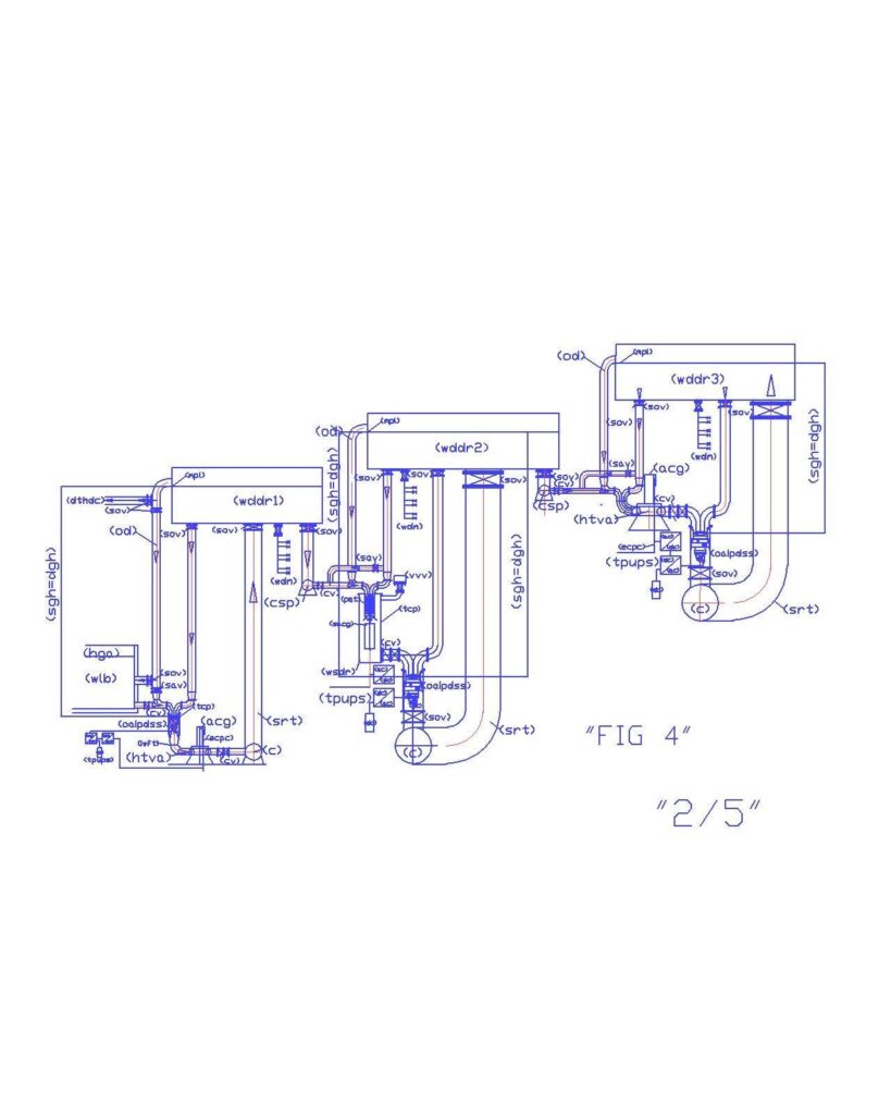
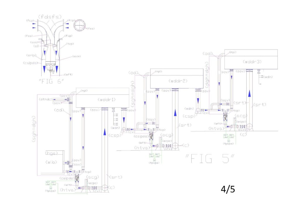
Legend Fig. 8 (4) : (acg) alternating current generator; (ai) axial impeller; (C) collector; (oipds) overturned intubated pump with dual suction; (csp) connection systems pipe; (cst) containment system tube; (cv) check valve; (dgh) delivery geodetic height; (dthdc) deviation towards hydraulic drainage canals; (ecpc) electrical current produced cable; (fcp) flange for coupling to the pump; (fdsfs) flanged dual supply and flow separator; (fss) flow separator in sheet steel; (htva) hydraulic turbine with vertical axis; (mpl) probe of the minimum or maximum level; (od) overflow discharge; (sav) supply additional valve; (sgh) suction geodetic height; (sov) shut-off valve; (srip) supporting ring for intubate pump; (srt) supply reservoir tube; (sss) shaped sheet steel; (tcp) tube containing the pump; (tpups) three-phase UPS; (wdn) water dstribution network; (wddr) water distribution and disconnection reservoir.
In these simple systems, the hydrostatic head, measured in meters of water column is chosen after having carefully calculated the load losses in the turbine and in the tubes, to put down the axis of the pump at the exact point where the positive dynamic pressure on pump alone can balance the resistances to the water circulation, including the turbine. The pump has only the task of winning the state of inertia of water inside the tubes that feed the pump and the turbine, consuming very little power, being positioned between two equal and opposite loads. The rotation of the pump, placed in such conditions, produces in full water column overlying the pump, that is separated from the surrounding static water, producing kinetic energy (1/2 * m * V2), derived from ( m * g * h), which is exploited in the turbine to produce electric energy. Even the loss of pressure in the valves and in the tubes may be charged to the kinetic energy developed by the water that falls from the upper reservoir, if they have been dimensioned correctly the passage sections. Assuming that the overall performance of the turbine and to the coupled current generator is 0.8. The useful power can be supplied by a turbine which fully exploits the payload Hu of 50 m, with a ducted pump which has a flow rate of 1 m3/s, will be Pu = η*1000*Q*Hu/102 = 0,8*1000*1*50/102 = 392 KW; while to let the pump rotate in conditions of equilibrium between the positive head and the turbine just a prevalence of a few cm of water column. Assuming you work with an electric pump that has the same scope, prevalence 0.2 and 0.7 output, the power consumption is 2.8 kW (1000 * 0.2 / 102 * 0.7). The ratio of energy produced and expense is 392 / 2.8 = 140.
No one has ever thought of being able to produce energy by drawing from static energy sources such as atmospheric pressure and the hydrostatic height on the pumps, although these are, always considered in the hydraulic calculations for determining the prevalence of plant and pumps and then, also saving energy in hydraulic lifts.
Infact, If it is possible to exploit the hydrostatic head to save energy by pumping water up to win the atmospheric pressure, it is also possible to transform the hydrostatic head favoring the atmospheric pressure into energy, not raising but pushing the static waters down, after intubation of the same and starting from the surface of water. As seen from Fig. 8, the collector (c), which collects the water outlet of the turbines, can be considered, such as the bottom of the tank (wddr), while the vertical tube (srt) the extension, therefore, the load loss to consider is that of an outlet in an open vessel, such as in submerged installations, in addition to only the load losses in the pipes, not those to overcome the difference in level. The laws of hydraulics are clear, both as regards the exploitation of Hga in the suction of the pump, both with regard to the loss of pressure in a hydraulic circuit in the open vessel, from which start the aspirated water and return those pumped. The positive hydrostatic head to be carried on the pump shaft is the sum of the useful height (Hu) request from the turbine plus the pressure losses in the pipes (pdc) and to the outlet (pds). Even the length of the water network that connects the tanks (wddr) may be charged to the hydrostatic head. In fact, if we increase the distance between a basin and the other, we need not increase the prevalence of the pumps but the hydrostatic head on the pumps that costs much less. Increasing the diameters of the tubes we reduce the height of the plants and the operating pressure. The prevalence to be assigned to the system and to the pump “H” is equal to the algebraic sum of: (+) Hgea (-) Pdc (-) pds, where:
Hga (m) = (sgh) geodetic suction: distance between the upper level of the water intake and pump axis. Hga, in our case, for energy purposes, is positive since the pump is subjected to the water level.
Pdc (m) = sum of all the system pressure drops, which, for the absorption of pressure energy purposes are to be considered with a negative sign. In our case, are represented by the descent tube, the special pieces, the resistance to the rotation of the turbine, the speed in the pipe (rst) of connection to the vessel.
Pds (m) = pressure loss at the outlet in the manifold and in the upper tank (V2 / 2g)
Never exceeding with the tube (rst) the level of the basin (wddr), by pumping in the direction of the atmospheric pressure, the prevalence of the plant tends to zero by balancing the loss of pressure with the hydrostatic head. Obviously, to have the maximum energy produced should concentrate the load losses in the turbine reducing the other, by expanding the diameters of the tubes and reducing the lengths. In fact, the collector (c) and the tube (rst) is represented of large size compared to other tubes to indicate the volumetric continuity of the reservoir.
In these systems dynamically we exploit the principle of Pascal: using the hydrostatic pressure of the upper reservoir to raise the water flow in the lower basin fed into the recycle loop thanks to dual fuel pump, without consuming energy. Besides the principle of Pascal, this possibility is confirmed by artesian wells where groundwater comes directly on the surface without the aid of pumps. It is not the pump to raise the water, but without the dual power supply of the pump the water could not have been inserted in the recycling circuit to be raised. In fact, the closing of the valve (sav) that feeds the left side of the pump, allows to feed such side of the basin with the water placed in the lower level, the mixing and the sum of the two flows, which occur in the pump, enable recovery of the maximum hydrostatic level of the reservoir without appreciable energy consumption. Reached that level, it closes the water supply to be lifted (sov) and opens again power supply with the recycled water of the upper basin (sav), until the water level is lowered again and requires a new lift of water. Obviously, this system can be used for large and small flows and large and small differences in height. Observing Fig. 5, the dynamic pressure that circulates in the right side of the pump it is also transmitted to the one that enters from the left side. The water with a lower hydrostatic pressure is inserted in the upper basin of the recycling circuit and therefore raised, but the turbine continues to produce energy almost to the maximum level if the water passage sections are adapted to the transmission of dynamic pressure of the upper reservoir. At the the exit of turbine water comes into the collector (C) which is also the bottom of the open vessel, which provided water, the static and dynamic pressure to produce energy in the turbine.
It is important to note that in these plants we realize synergies not only between the pumps and turbines, but also between the hydraulic principles on which they are based. Il vantaggio energetico lo abbiamo facendo la differenza tra l’energia prodotta nella fase di discesa delle acque e quella consumata nelle perdite di carico, escludendo quelle della risalita delle acque perché nei bacini sempre pieni, a volume costante, l’acqua non deve essere sollevata; disproving also the myth of back-pressure at the exit of turbine because the static pressure is not opposed to the kinetic energy, except for the friction between the molecules, due to the speed difference (V2 / 2g). The representation is symbolic and shows only one pump per plant, but as in the current lifting systems, there can be many groups of pumps – turbines in parallel, as long as each group has at least one orifice connected directly to the upper reservoir with the dynamic pressurization tube. With the symbol (c) indicates the delivery manifold that may be common to more than one pump-turbines groups in parallel, as long as a large cross section to reduce frictional pressure losses with the walls of the tube. However, only the collector (C), the feeding tube (srt) and that in connection with the next facility (csp) are in common. In fact, each pump, pumping down, producing kinetic energy in its own tube, which dissipates into the turbine, specially dimensioned, therefore, the rise of water to the tank (wddr) occurs without energy, just based on the principle of communicating vessels. Also the connection between the various tanks (csp) must be of large cross section, having to feed the dual power supply of the next lifting pumps, which can be placed at many kilometers away. When there is no withdrawal from the water network (wdn), which consumes the water, there is no need of lifting water, so the system only serves to produce energy. In this case, also the left side of the pump is fed from the upper reservoir through the remotely controlled valve (sav) and we have the maximum of the energy produced. When, instead, because of the network levies the level of a tank (wddr) lowers, the control system, based precisely on tank levels, closes the valve (sav) of that tank and automatically, the left side of the pump is fed from the bottom basin (wddr) through the check valve (cv). Obviously, the operation involves the lowering of the lower basin level, and the control of the level of that basin, in turn, closes the valve (sav) and the water that feeds the left side is taken from the place at a basin still lower level. All this takes place while the pump and the turbine are always in rotation producing energy. Therefore, while in the current based on the levels of the automatic water lifting systems puts into operation a number of electric pumps increasingly higher to compensate the withdrawal from the network, in the plants in question the electric pumps are always in operation. Are valves (sav) that determine where to get the water that feeds the left side of the pump. The number of the valves (sav) that are closed, and the closure time, depends on the time it takes to restore the nominal level that corresponds to the exhaust infinity share of overflow (od). As can be seen, in the hydraulic connecting circuit between the initial reservoir (wlb) and the first basin (wddr1) the valve (sav) is positioned on the exhaust pipe (od). In fact, the level of the reservoir (w ddr1) must be maintained always at maximum water level (mpl), providing the water that comes from the overflow. When lowering the (wddr1) level, closes the (sav) and opens the (sov), allowing the water supply directly by left side of the pumps through the initial basin (wlb) through the check valves (CV).
Chapter 3
Italian demand patent N. 102016000058416 del 07/06/2016
FLOATING SYSTEM WITH EXTRUDED POLYETHYLENE PIPES, RIBBED, REINFORCED AND FILLED WITH POLYSTYRENE.
Abstract
The significant delay in the development of the exploitation of marine resources and the protection of global environment is due to many factors, among them the lack of economic floating systems and unsinkable. However, such systems could not be studied in detail without also provide technical solutions that can lead to colonization by mass of ocean flat. In fact, at present, it does not make sense this colonization, being inhospitable ocean flat for human life, both because water desalination is not sustainable, both because from the point of view of food, the ocean flat are not productive. The fish production is concentrated in areas close to the coast, where the wind and water currents allow the production of phytoplankton and zooplankton, and thus the production of food for the great variety of fish species and for men. However, the ocean flat could become the most rich source of human nutrition, because the invention of “Floating system, hydroelectric, desalter, extractor of calcium and carbon from marine deep water.” allow to desalinate, produce energy and abundance of fish at the same time, raising to the surface a part of the deep water, rich in calcium and carbon, dissolved by high hydrostatic pressures. These plants will produce phytoplankton, zooplankton and alkalinity, also fighting water acidification and global warming. In this project have been incorporated extruded ribbed polyethylene pipes, filled with polystyrene, to make unsinkable plants. Of course, it must also be made unsinkable floating islands and connecting roads that will serve around these plants. Therefore, even though the valid existing flotation systems used for the construction of marine shipyards, should give place to a large series productions that can be only realizing them by extrusion. Even sea transport of these tubes must be sustainable and economic, by assembling, in shipyards major floating structures and bulky and transporting them in place by tugboats.
Description At the state of the art, although there are valid flotation technologies with modular elements in polyethylene coupled in a vertical and horizontal direction by means of profiles of galvanized or stainless steel, these modules, realized by molding, have a high cost of production. They can be used, as are, to realize houseboats, marine and lacustrine sites, temporary roads etc. But for a series of great use, such as that suggested for the realization of “Floating system, hydroelectric, desalter, extractor of calcium and carbon from marine deep water”. and the induced activity that will result, it is considered much more economic the following solution, that It estimates to raise the floating elements directly by extrusion, such as the current of polyethylene pipes, with the only difference that these pipes will be produced with perforated external ribs at regular steps, so that they can be coupled to each other and to the metal structures of containment or support , in the various possible compositions. Furthermore, inside the tubes can be inserted some radial ribs in tubular profiles, mounted on a central tubular axis, arranged in a regular step as a function of the immersion depth, certified with a specific report calculation on the resistance of the polyethylene and metal material. Finally, the tubes will be made unsinkable by means of the sintered polystyrene foam filling, which has a volumetric mass between 10 and 40 Kg / mc, and is then constituted by the average of 98% air and only 2% of pure structural material hydrocarbon. Therefore, any damage to a floating hose, would not cause the immediate filling with water and sinking, but would allow a large margin of time to repair the damage or replace the damaged pipe. Whereas the tubes obtained by extrusion products can be of any length, to save costs, it is not hazardous hypothesis to achieve the production facilities close to the sea, to assemble systems in adjacent coastal shipyards, tow them and transport them directly in the final working area, where it would be more difficult and expensive the assembly work, in general. But, above all, in the specific case of the “Floating system, hydroelectric, desalter, extractor of calcium and carbon from marine deep water”, because of the complexity and importance of the work to be performed, it is preferable that the site platform, as represented in the Fig. 9 is assembled in a shipyard with all mounting equipment mentioned in the legend (bridge cranes, hydraulic cylinders, working loft columns of electrical winches) and transported on site by a tugboat.
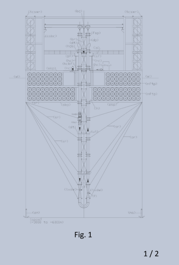
FIG.9
Fig. 9 shows the starting point, ie the float construction site from which arises a “fFloating system, hydroelectric, desalter, extractor of calcium and carbon from marine deep water”. This facility to extract the calcium and carbon dissolved from the high hydrostatic pressures in the deep water must come down over 4000 meters deep. Assuming to provide a system that goes down to 6000 meters, with steel pipes Dn 1400 from the mechanical strength point of view, the two parallel pipes for the 6 km long Dn 1400 that serve to implement the system may be of the API series 5LX, grade X 70 with a thickness of 10,31 mm, in steel with the following characteristics: Ks = 70.000 p.s.i = 49,2 Kg/mm2; Kr = 82.000 p.s.i. = 57,6 Kg/mm2. The marine water has density 1,025 kg/L therefore at 6.000 m di profondità exert a pressure on the seabed equal to 6150 m of water column (1,025*6000) = 615 Kg/cm2 = 6,15 kg mm2. Therefore, the stress that the water exerts on the piping material is much less than the minimum yield strength. This means that the pipes cannot be deformed if the pipes are full of water, while having minimum thickness. In fact, the problem to be solved are the stresses due to the weight. It is advisable to use high quality pipes with low thicknesses. The tube X 70 Dn 1400 taken into consideration it has the minimum thickness of the series (10.31) and weighs 358,73 kg/m, that increase of 15% to take account of the flanges, bracings, etc., the whole load becomes (12.000*358.7*1,15) equal to kg 4.950.474, subtracted of the upwards hydrostatic thrust, equal to (4.950.474*1,05/7,8) pari a 666.410 Kg, subtracted of the upwards hydrostatic thrust, equal to 92.096 mm2 (1.422,4*3.14*10,31*2) which would have a maximum stress in tubes placed at the top (that support the entire load) of 40,91 kg/mm2 (3.767.710/92.096).
There is no cranes in the world that can support the weight of nearly four million kg, therefore, to be able to build the facility which raises calcium and carbon from the deep waters is necessary to carry on a temporary construction site platform with the mounting equipment they serve to the laying of the pipes. At the center of this platform is accomplished the immersion hole (ih), of such dimensions as to contain the lifting cylinders (hc) with the useful travel of 6 m, which will be mounted on a bridge crane (bc) with three hoists, which serve for the mounting and the vertical transport of pipes 12 m long bars, the relative bearing structure (SSBC) with the frames in more supporting floors (tcswr). Each floor contains an electric winch with its rope (sr). So the tubes have dropped in deep sea while they are mounted and the final framework are supported simultaneously from above and from the four sides of the platform. The lateral suspension points increase as increases the depth of immersion, both to support the load, both to contain the lateral stress, due to ocean currents, both to contain the unitary tensile stress, due to the weight of the tubes. The flanges, visible from the drawings, will be welded because the bolt sections represent a weak point in the tensile strength. The flanges are of a special type, used as supporting bars for the descent of the pipes (dt-ut), to connect the bracing and the rope pull (sr). Whereas the linear meter weight of the pipes in the water with flanges and braces is estimated at about 314 kg (3767710/12000), each tube bar of 12 m, including accessories weighs approximately 3768 kg. Therefore, if we make a link to the platform every 60 m depth with ropes of 30 mm diameter, the total breaking load of 218,700 kg (3 x 72,900) we support the entire weight of 60 m (18,400 kg) with a safety factor of to 11.6 without regard to the load supported by the tube itself, which, as we have seen entail a tensile stress of 40.91 kg / mm2.
As seen from Fig. 9, the floating structure using a hydraulic system for the vertical movement of the column of tubes (dt) and (dp), consisting of two vertical hydraulic cylinders simple effect (hc) with a stroke of about 6 m, which by discharging the hydraulic oil in the tank of the hydraulic unit (othcu), lowering the cylinder rods and they lower the entire column of tubes as they are assembled and are mounted also the bracing with the aid of the bridge crane (bc) and the loft (ls). The pipelines will be pre-assembled at the factory with the support flanges of 12 m elements, painted with epoxy resin cycles inside and outside, leaving only the edges to be welded in place unpainted to be painted on site with the same cycle. The braces will be hot dip galvanized. The decline of the pipes will be assembled by placing the column on the brackets (hcb) mounted on the frame (sf) located across the diving hole (ih). The frame (sf) is driven by hydraulic cylinders (hc) embedded in the structure of the dive hole (hi). The brackets (hcb) are dimensioned for the entire load-carrying (3,767,710 kg). Assuming to work with a pressure of 250 bar to support all loads during assembly. The section of each cylinder will be approximately 7535 cm2 (3,767,710 / 2 * 250), which corresponds to an internal diameter of 98 cm. A bridge crane with three hoists with capacity suitable for the lifting of feeding tubes and bracing elements to assemble and fall into the sea with the help of a mezzanine (ls) that allows you to work on two levels. To reduce the stress due to the weight of the pipes estimated above, three cables have been provided (sr), (already mentioned above) that connect the individual bars of the tubes to the floating platform (sbp). These ropes (sr) from the winches contained in the multi-storey frames (tcpwr) arranged on the outer perimeter of the upper floating platform, roam the property and enter into the dive hole (ih) and lugs with snap hooks are superimposed on the perimeter of the hole of’ immersion on corresponding six pegs, according to the dive order which must have in the descent of the pipes. In fact, every sixty meters (equal to 5 bars of pipes), six strings will snap to ribbed flanges, three for each tube, while the inner side will be connected with the braces (br). Therefore, we will have n. 600 workstations of winches (6000/60 * 6) 150 arranged on each side of the platform (sbp) with the lugs already brought close to the diving pit. Not being able to wrap the whole rope on a winch only, each frame (tcpwr) brings more superimposed winches. When it runs out the rope of a winch is released and attached to the winch with junction elements of the lower floor, until the entire frame it runs out and is replaced. The strings that start from periphery of the platform (mftp -sdp) not only serve to lighten the axial traction of the tubes but also for bracing the entire column in all directions. Obviously, even the naval type anchors (na) can be dropped with stations of winches (tvpwr) located at the periphery of the floating structure. when Assembly is completed it will support the load with a fixed clamp brackets (cb) on the structure (for this purpose the last bar of piping will be flanged with a sufficient amount of bolts) and will be fixed stably across the terminals of the 600 positions of winches on the periphery of the structure. After the laying of the pipes that come down in the sea bed are fixed permanently on the metallic structure of the platform, after disassembling all of construction equipment, in place of which it is mounted the desalination plant, as seen from Fig. 11 of the chapter 4.
Legend of Fig.9: (apos) abyssal plain ocean seabed; (bc) bridge crane; (bcb) bracket cross bracing; (br) bracing; (cb) clamp brackets; (dt) descent tube; (f) filter; (fsp) flange for support pipe; (hc) hydraulic cylinder; (hcb) hydraulic clamp brackets; (hcbf) hydraulic clamp brackets fixed on supporting base platform; (ih) immersion hole; (itia) intubate turbine with incorporate alternator; (ls) loft in steel; (mftp) modular floating tube made in polyethylene; (na) navy anchor; (osip) overturned submergible intubated pump; (othcu) oil tank and hydraulic control unit; (sbp) supporting base platform; (sfep) special flanged end pieces; (ssbc) support structure bridge crane; (tvdwi) throttling venturi deep water intake; (tcpwr) transportable chassis with many electric winches for the descent of the ropes; (ut) uphill tube; (wl) water level.
Although calculating accurately the weights of the tubes to be supported and the system of final desalting, the immersion of the final framework platform is only ascertains the end of the assembly of all the suspended tubes which descend in the ocean depths, after disassembly of the equipment construction and mounting them in place of the desalination plant. To achieve the final structure of the platform floating floor, a percentage of floating tubes seats above will be filled with compressed air at the maximum expected operating pressure of the dive. At the end of the work, by means of a threaded connection, with by-pass valve, the air may be replaced with water, if the platform has to soak in the water more. If the platform must climb must be added to the structure other floating modular elements.
We do not enter into the merits of the tube manufacturing process but simply identify the production technology, because, extrusion occupies a prominent position for versatility and breadth of application. The extrusion technology is an operation that operates continuously and in stationary conditions to produce different kinds of artifacts characterized by symmetrical or asymmetrical sections that are repeated identically along the extrusion axis. In its essential lines, the production of a polyethylene pipe is very simple. A production line of a polyethylene tube is constituted by a loading hopper of the polymeric material granules which feeds an extruder, which is constituted by a screw pump which rotates, with very precise coupling, inside a heated cylinder. Between the cylinder and the screw core is located in the molten material to be extruded, which is then forced through an extrusion head. The molten material rotates at a lower speed than the screw, and then is pushed forward from the crests of the threads of the screw and is then forced through an extrusion head. Having planned to accomplish a tube with perforated ribs which serve for reinforcement of the tube and for the fittings, the holes must be made by means of a punching the top of the entry into the extrusion head, when the material is still plastic, in sync with an eventual slowing of the speed of advance of the material in the extrusion head. It does not matter if for processing requirements will produce the punching of the slots instead of holes. The function that must carry out the holes or the slots is identical.
Below the main features of a low and high density polyethylene pipe ( LDPE) (HDPE)
Specific gravity at 23 degrees C. (g/ cm3) 0,917 – 0,925 0,95 – 0,96
Melting point crystallographic (oC) 105 – 115 125 – 135
Tensile strength (kg /cm2) 80 – 170 250 -350
Elongation at break (%) 400 – 650 100 – 300
flexural rigidity (kg / cm2) 800 – 900 9.000 – 12.000
Considering that polyethylene pipes for floating shall be of a size large enough to perform their function may also be used, in part, as the descent and ascent of the water pipes that extract the calcium and carbon from the ocean depths. In fact, if we compare the breaking strength between the pipe (HDPE) of 250 kg / cm2 = 2.5 kg / mm2 compared to steel Bees 5LX which has a breaking load of 57.6 Kg / mm2, we can say that the ‘steel is twenty-three times more resistant high density polyethylene, but considering that the polyethylene pipes are produced with thicknesses at least four times higher than those of steel, we can say that the difference in resistance is reduced to about 5.75 times.
But whereas the static stress may also be doubled in the steel without serious problems, we can say with certainty, that a third of the way into the depths of 6000 m provided the example of installation concerned, you can achieve with HDPE pipes, lightening the load to be supported by a third, being the pipes HDPE lighter than water.
Moreover, whereas the polyethylene is a synthetic polymer based on carbon is not recommended for use with the high pressures that might lead to phenomena of dissolution of the synthesized molecule. In case of use of HDPE pipes as descent and ascent in the tubes of calcium and carbon extraction systems by ocean depth, the transition from steel to polyethylene is realized by means of flanged coupling and all the axial load due to the weight of the pipes in underlying steel must be supported by the platform peripheral winches (tcswr) not by the central hydraulic cylinders (hc), even during the assembly phase. The strong ribs of the tubes, designed for mounting of the floating solutions will also be useful for this use, both for the support, both for the lateral stiffening. For the use of the tubes as floating, he was expected the internal reinforcement of the same by means of a radial pattern of structural steel, with six rays, coinciding with external ribs, where they will be applied loads and mechanical linkages. La raggiera sarà montata e fissata su un asse tubolare e fissata con viti a mordente sullo stesso, mentre la parte periferica dei raggi è tenuta insieme da una fascia di lamiera calandrata. Nella Fig. 10 si riporta la sezione tipo di un tubo di galleggiamento.
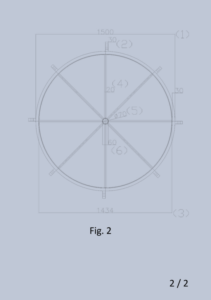
FIG. 10 (2)
Legend Fig. 10: (1) polyethylene pipe outside diameter 1500 mm, thickness 30 mm; (2) outer polyethylene pipe rib 80×30 with mounting holes; (3) calendered sheet 100 * 5 mm outer diameter 1434; (4) diameter steel round 20 mm; (5) smooth bore tube diameter 70 mm, lung. 80, thickness 3 mm; (6) smooth bore tube diameter 60 tickness 3 mm, length equal to the tube 1.
As mentioned above the flotation tubes for the importance that will assume should be certified both for the outer material in a low or high density polyethylene, both with calculations regarding internal reinforcements, in order to also locate the maximum draft of the same. Furthermore, after the mounting of the reinforcements inside the pipes will be filled with expanded polystyrene, and after the evaporation of the expansion gas definitively capped with circular plates welded polyethylene. The expanded polystyrene not increase the mechanical strength of the pipes but will prevent the entry of water in case of breakage for a long time to allow the repair of the damage without danger of sinking.
The Sintered Expanded Polystyrene (EPS) is derived from polystyrene (chemically called PS) is a major plastics which are derived from petroleum. The EPS is a lightweight, rigid foam material, derived from petroleum composed exclusively of carbon and hydrogen atoms. It ‘a closed cell structure capable of retaining the air inside them. At the compact polystyrene is a rigid material, colorless, transparent which finds application especially in the packaging and in those fields which require an easily workable polymer, transparency, good thermo-mechanical performance. The EPS is one of the most important forms in which the polystyrene is employed. To obtain it melts a blowing agent in the polystyrene (commonly pentane) and it is treated with other additives to confer resistance to fire. The product is presented in the form of glassy appearance granules (beads), of varying particle size (0.3 to 2.8 mm) according to the purpose which it is intended.
The expansion, namely the chemical-physical process that leads to the formation of “beads” of polystyrene, is by administration of the energy expandable polystyrene – the raw material – without the use of CFC. Putting in contact the beads thus obtained with water vapor at temperatures exceeding 90 ° C, pentane contained in them expands causing an increase of their initial volume up to 20-25 times and by forming inside them a closed cell structure that It holds within itself the air and gives the product its excellent thermal insulation properties. To obtain the EPS is still need a further operation called “sintering” which is the welding process and the compaction of the expanded polystyrene beads; this implemented happens by subjecting the granules again to the action of water vapor that joins them together, to form countless articles: blocks of several meters, the molded using a thermoplastic process of “injection”, etc. To give the precise technical features products are added various additives. It is used for water repellent of stearates. The sintered expanded polystyrene has a density generally comprised between 10 and 40 Kg / mc, and is then constituted by the average of 98% air and only 2% of pure structural hydrocarbon material. Pentane used for expansion, it evaporates at the end of the process in which, against every stereotype, are not used chlorofluorocarbons that are harmful for the ozone layer.
Technical features:
The density of the expanded polystyrene is between 0,02 e 0,06 g/cm3.
The thermoplastic polystyrene is physiologically harmless and also allowed for packaging of food products. The same also applies to the heat-insulating material. In the production of EPS they are not used, nor have ever been used, chlorofluorocarbons – CFCs – harmful to the ozone layer surrounding our atmosphere. The EPS has no nutritional values able to sustain growth of fungi, bacteria or other microorganisms so it does not rot or mildew. The EPS does not constitute food for any living being. The foam does not burn a high flame, but softens at from 95 ° C to 230 ° C gives off decomposition products are flammable; between 450 ° C and 500 ° C ignites spontaneously. In the combustion of polystyrene are formed of acrid odor gases (CO, styrene, benzene, toluene, anti-flame agents) which, however, are not toxic, excluding CO.
Chapter 4
Italian demand patent N. 102016000058018 del 07/06/2016
FLOATING SYSTEM, HYDROELECTRIC, DESALTER, EXTRACTOR OF CALCIUM AND CARBON FROM MARINE DEEP WATER.
Abstract
The state of the art in the development of desalination and demineralization treatment of marine and brackish water has been affected, along with industrial systems, purification, energy, food and protective of the environment, the absence of synergies between the pumps and hydraulic turbines and from the incorrect approach with the gravitational force, which must not be won by the hydraulic lifting but sustained, with one-way movement of water, especially in the gravitational direction, in the sea, in large basins, in open tanks. With simply overturned pumps coupled to the turbines can produce low-cost all the energy you need; continuing the descent and ascent of water in deep waters, for the venturi effect, we can suck and lift small percentages of deep water with high calcium and carbon percentage solubilized in them, that arrived at the surface, producing phytoplankton and alkalinity, increasing the abundance of fish and combating acidification and global warming;
while on the floating platform, made with extruded and ribbed tubes made of low density polyethylene, blown in them polystyrene foam to make them unsinkable, with the triple synergy between the dual fuel pumps, turbines and the marine water recycling, by applying known hydraulic principles for centuries, as that of communicating vessels, the laws of Bernoulli and Pascal, placing, strategically, the electric double suction pump between a high positive hydraulic head and the turbines, we can desalinate large quantities of water, simply transforming a vertical tube in a ionic exchanger and recycling pipes and mixing in the energy producers, while the anionic and cationic synthetic resins, circulating contained in perforated polyethylene spheres as sieves. These spheres, floating climbing ion exchanger and descend for gravity emptying water in downhill tubes. By means of diverters change the path compared to the flow to be immersed in the washing tanks and regeneration of the resins, and reinserted again, indefinitely, in ion exchange circuit without interruption of the desalination cycle and energy production and without costs for heating the water or replace the membranes. If we want to exploit the immense riches of the sea, floating solutions have no alternative. The systems must be designed supported from above, since it cannot exist electromechanical equipment that can work to the abyssal depths. The sustainability of global systems is not only based on high technologies and special materials but above all on the physical basic principles, chemical, hydraulic and mechanical.
Description
The scope of this invention is the exploration of new sustainable plant systems for survival for the human species in the sea. The floating solution has no alternative, since no electromechanical equipment that can work to the abyssal depths.Barely resisting homogeneous materials such as steel. Therefore the plant must be lowered and supported from above, the water heavier materials, such as steel will work in traction, contrary to when it occurs in applications realized at atmospheric pressure, where the materials work by compression, by downloading all the forces on support bases. This is a new way of designing systems which has advantages and disadvantages. For myself, are a lot more advantages. In fact, this plant is the core around which men will develop small or large human agglomerations in oceanic areas, fully autonomous from the energy and food point of view. We all know that offshore the oceans life forms of phytoplankton and zooplankton are very slim because life in the marine waters grows mainly along the land coast, where, because of the winds, waves and underwater currents are generated updrafts that bring to the surface the nutrients bound in the seabed, especially rich of organic and inorganic carbon. Questi nutrienti, riportati in superficie, producono una fascia superficiale di fitoplancton per mezzo della fotosintesi clorofilliana, che costituisce l’alimentazione di organismi animali acquatici; pertanto, nella stessa zona si crea anche spontaneamente il cosiddetto zooplancton di varie dimensioni costituito da microorganismi (alghe unicellulari, protozoi etc.), larve, piccoli animali (come i crostacei che formano il krill), ma anche organismi di una certa mole come meduse e alghe pluricellulari (quali i sargassi). The set of plant living beings and animals form the plankton, which is characterized by a high specific biodiversity rate from which they draw the life also fish species more.
To the Wide of the oceans, although the seabed there are huge stores of carbon accumulated over billions of years, the rise of carbon and precipitated calcium millennia can not occur spontaneously due to great depths, so you need this set of inventions, especially, considering that over areas off the oceans are not subject to high and tsunami waves. In fact, the frequent earthquakes that occur in the deep sea, are rarely perceptible in surface water, if we have the foresight to realize these works at a suitable distance from the coast. The translation of the word “tsunami” by the Japanese, means “wave in the harbor.” It is a series of waves which are generated as a result of sudden movements of the seabed due to earthquakes, underwater volcanic eruptions, landslides, meteorite impacts. The most devastating Tsunami are caused by vertical movements (lifting or sinking) of the earth’s crust along faults and edges of the ocean shelf. Considering that with current technology we can achieve unsinkable and stainless frames of plastic and mounted on them other technologies that produce energy, desalinate and potabilizzano the waters, these inventions may begin the colonization of ocean space they occupy 71% of the earth’s surface.
In fact, once solved the energy problems and desalted water, for the construction of the islands, we have sufficient energy to develop comfortable and light homes. But if we also think the technology used for the construction of the Hanging Gardens (posing the land on plastic crawl spaces covered with filter cloth), we could also bring the cultivation of the above-ground vegetables and have immense advantages, with a capacity of vegetable food and fish production now unimaginable. If we use the greenhouses, productivity, already tested, it is higher than 50%, while the desalinated water can be recycled and purified, without polluting the land flaps. But in this patent application we are concerned only the central core which produces the initial state of life, which does not exist today, but paradoxically, it could also be a better life than the one we live in metropolitan hives, not being able to imagine on these islands heavy skyscrapers and heavy vehicles that pollute the environment. However, we can imagine a life with all the technological comforts, air, water and nutrition, most of the best land and less danger of natural disasters.
So, this synergistic system focuses on four sustainable systems not yet realized on planet Earth: 1) The production system of hydroelectric power from static waters and water recycling, described in Chapter 1 and 2
- The sustainable modular floating system by extruded polyethylene and reinforced pipes, described in chapter 3.
- 3) The lifting system of calcium and carbon dissolved in the ocean depths, described in this chapter.
- The sustainable system of vertical water desalination by means of ion exchange, coupled to the energy production, described in section 1.
This vertical system allows to have the desalinated water produced in the highest point of the system to distribute it at a considerable distance by gravity to artificial islands, which will develop around these plants, which form the heart of new industrial and economic activities, connected with floating roads.
The starting point for the construction of this system is the floating construction of Fig. 9 from which comes a hydroelectric synergistic system, water maker, calcium and carbon extractor from the deep waters of Fig. 11.
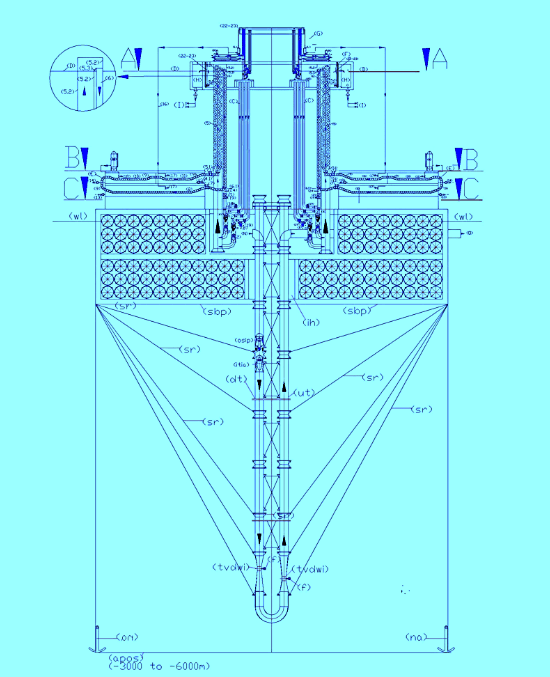
Fig.11 The following legends integrate the legend of Chapter 1, as the desalination plant of chapter 1 (Fig.1) is mounted on the floating structure of Chapter 3 (Fig. 9) which supports the plant designed for the extraction of calcium and carbon from the deep waters, after mounting the underlying pipes and dismantled the construction site equipment.
Legenda alfabetica della Fig.11:
(A) arrival basin of salted water; (B) salt water inlet filter with built-in check valve; (C) Water recirculation tube and dynamic or kinetic pressurization of the electric pump; (D) Nominal upper basin level; (E) washing and regeneration circuit of ion exchange resins; (F) upper reservoir mixing and overflow desalinated water; (G) Mini implant of deionized water production; (H) desalinated water storage basin; (I) desalinated water distribution network; (L) demineralized water accumulation tank; (M) regenerating liquid tank; (N) Entrance descending water; (O) exit water with calcium and carbon.
Legenda numerica della FIG.11:
(1) overturned dual supply pump on the suction side; (2) submerged turbine with incorporated alternator; (3) nominal level of the water basin to desalinate; (4) pipe for supplying water to desalinate; (4.1) special piece for introduction spheres with resins in the ion-exchange tube (drilled in the lower part); (5) tube of ion exchange; (5.1) perforated truncated cone embedded in the tube 5; (5.2) special piece to eject spheres from the tube 5 (perforated on the entire outer surface and connected to the tube 6 by means of the slide 5.3); (5.3) metal sheet slide for the guidance of the spheres in the tube 6; (6) tube of descent spheres for the emptying; (6.1special piece for the deviation of the spheres from the ion exchange circuit to the regeneration circuit (drilled at the bottom for water drainage); (7) automated guillotine valves for stopping movement spheres (are always open when the minimum level probe indicates that the tube 6 is empty of water; (7.1) automated guillotine valves for stopping movement spheres (open one at a time); (8) first tunnel for immersion wash of the resins; (9) guided route of the spheres in the immersion tunnel with an open frame of stainless steel rods by ascents and descents with slides for the collection of the of the spheres emptying liquid; (10) tunnels for regeneration of the resins in immersion; (11) second washing immersion tunnel of the resins; (12) pump suction sludge from arrival reservoir; (13) electric pump suction of resin washing sludge; (14) electric pump suction of resins regeneration sludge; (15) Support frame demineralisation plant; (16) supply pipe demineralized water; (17) float valve for feeding demineralized water; (18) float valve for regenerating liquid supply; (19) motorized shut-off valve; (20) Manual shut-off valve; (21) check valve; (22) salinity control probe; (23) PH control probe. (24) minimum water level control probe of spheres emptying tube; (25) submerged agitator.
Description of calcium and carbon lift system from the deep waters.
As can be seen from FIG. 11, the water enters from the (N) in the “U” shaped tube that goes down in the depth ocean and exits (O). Thanks to the principle of communicating vessels, the internal and external pressures to the immersed pipes are the same. This not only allows you to withstand enormous pressures, but also allows you to use the weight of the water column on intubated pump, oriented downwards, to create intubate currents with very low energy consumption. In fact, by calculating the position in which we install the electric pump, under the head, do we make sure that the curve of the duct resistant and the pump curve that we insert for the circulation of water meet each other on the zero line of the geodetic head which is equal to zero (coinciding the levels of suction and delivery on the pump). Therefore, also the pressure and kinetic energies in the suction and discharge are reset each being P1 = P2 and V1 = V2 (due the water intubate column on the pump suction specially calculated) according to the relation H = 0 = (P2 – P1) / γ + (V22 – (V12) /2g. Obviously, no pump works with zero head and the pump just begins to turn, finds its point of operation with a few centimeters of prevalence, and a deviation from the nominal flow rate, which depend on the accuracy of the calculation. Another basic principle on which are based these systems is the Bernoulli theory that explains the venturi pumps that can help to suck from the abyssal depths, without mechanical a part of the water or sludge present in the seabed. In fact, the law of bernoulli states that: “If the fluid is flowing in a conduit provided with a constriction in which V1 and V2 are the speeds, S1 and S2 are the respective surfaces of the sections, P1 and P2 manometric pressures measured in correspondence of these sections, for the principle of conservation of energy is established the following relationship: P1 + ½ d V12 = P2 + ½ d V22. The constancy of the value of the expression shows that, the greater the speed difference in the respective sections and the smaller the pressure difference, and vice versa. Therefore, the effect of the pressure drop across the tube which occurs in the bottleneck, from the outside, enters the tube in which circulates the water surface, a percentage of the seabed water, which rises to the surface. This water is rich in many minerals because at very high depth, even the insoluble substances are solubilized. They are especially rich in calcium and carbon precipitates in the backdrops from the origins of the Earth. The calcium and carbon, rising to the surface, are diluted with the water surface and return to react according to the following reaction, which characterizes the alkaline balance of the water at atmospheric pressure: Ca2+(aq) + 2 HCO3- (aq). ↔ CACO3 + CO2 + H2O, reproducing the surface of the calcium carbonate hydrogen that exists only in solution: CO2(g) + H2O + CaCO3(s) ↔ Ca(HCO3)2. The hydrogen carbonate, in the right proportions makes possible the formation of calcareous shells and bone structure of the fish species, the restoration of coral reefs, and will help to restore the marine PH to the original level, before the industrial era, while the other components, especially based on carbon, create the conditions for developing phytoplankton and zooplankton. Unfortunately, the average depth of the ocean waters, in correspondence of the abyssal plains, oscillates between 3000 and 6000 m, but in return are characterized by the absence of the surface waves. This allows us to design completely floating rigs, which are anchored to the far seabed can be kept in acceptable limits its position, despite the sea currents.
On the fundamental importance are the water pumps to be used, which must be protected from the fish species of great size that could put them out of operation. For this and other practical reasons were chosen for the semi-axial and axial pumps ducted, for which work must only be dropped inside of the lifting pipes and resting on a ring welded inside the tube. But it is preferable that these electric pumps are slightly modified so that they can work on the descending side of the tubing (dt) with the suction side at the top, moreover, do not have the wide range of prevalence that we use in terrestrial plants. It ‘convenient to work with very low heads to conserve energy. The task of winning the circuit resistance is entrusted to the energy of surface water position. The power cables must exit the suction side, which will have its own lifting eye.
Assuming provide a calcium and carbon extraction installation on a seabed place at a depth of 6 km, and then, with the descent of the pipe 12 km in total (dt) and rise (ut), Dn 1400 which also it contains the electric pump in tract (dt), with a flow rate 4.000 L/sec, V = 2,6 m/sec, the load losses in m / km calculated with the formula of Bazin (1.000*4*V2/C2*D) wherein (C= 87/(1+2g/√D) and a roughness coefficient g=16, sono 4,11 m/km, for a total of 49,32 m. The pressure drops localized in 2 venturi bottlenecks with D2 = 700 mm (V2 = 10.4 m / s) is equal to 5.51 m (2*0.5 * V22/2g); the load losses in the 180 degree curve, is equal to 0.34 m (2*0,5* V12/2g), the load losses in the element of the final water outlet estimated at 0, 34 m.
Therefore, the head necessary for the circulation of 4000 l / sec in this circuit is about 55,5 m (49,32 + 5,51 + 0,34). Installing the electric pump at a depth of 54 m from the surface (55.5 / 1,025) whereas the sea water density is 1,025 t / m3, we will choose an electric pump, which works to give the required flow with a prevalence of only 0.2 m, because no pump can work at a zero head. It will be the effective hydraulic resistance of the circuit to establish the precise point of operation of the pump but always within a few cm of difference regarding the prevalence. Considering a 70% total return of the electric pump, the power consumption would be: (N=Q*H*1.025*102*0.7) = 11,5 Kw.
This plant designed for the carbon and calcium lifting can also produce energy. In fact, for example, if we install the pump under a ducted hydraulic turbine, which works with the flow rate of 4000 L / s and a pressure drop of 15 m, we do not increase the engine power of the pump, it is sufficient to install the pump and the turbine to a depth of 69 m instead of 54 m due to other losses of the circuit, calculated above. If the turbine efficiency with its alternator is 0.8, the energy produced will be 470.58 Kw/h (4000*15* 0,8/102). In fact, this circuit is totally open to the surface and with the intubation of surface water, once passed the state of inertia, in the descent phase develops kinetic energy fed continuously from surface. All the weight of the 69 m water column acts on the pump, the turbine producing the energy calculated above (that was subtracted of energy loss in the tubes (54 m). There are no energy costs for lifting water, since the water must not exceed the sea level. An open circuit is not similar to a closed circuit, for the mere fact that the dynamic pressure in the closed circuit can not renew with the entry of new water, as is the case in the open circuit. In fact, the renewal of the dynamic pressure is no more than the kinetic energy of the water surface that goes to the place of water displaced in depth. This energy can only exist if it picks up water from the surface one way and places the pump to the depth calculated to overcome the pressure losses of the pipes and the turbine with the mass of the ducted water column, which moves inside the tube , under the atmospheric pressure. At the exit of the pump and the turbine, it can be said, that the water does not have weight, not having to overcome the sea level. As written, just overcome the friction resistances, which can be overcome by increasing the positive head on the pump, without increasing the power of the engine which drives the pump. The hydraulic principles on energy conservation legislated by Bernoulli are limited to the comparison of pressure and speed of the water, showing that energy is conserved because it increases the velocity decreases the pressure and vice versa. Do not apply to open circuits, inserted in the hydraulic volumes more, feed them endlessly. In such circuits, without the inclusion of the turbine, the excess energy produced in the descent of the water would dissipate into heat by friction in the pipes and the pump outlet, together with the other load losses already calculated in the above example (54 m). This means that the principles of conservation of energy are always valid, but in a much larger system, which also includes the principles of thermodynamics and external energies, such as gravity, that participate otherwise if the mass is moving or stopped. Counts above the direction of movement, the speed, the dynamic pressure in the passage section. Nothing to do with the static pressure, which not being in motion, can also be transmitted with a small tube, but does not serve to produce energy. So, creating open energy circuits that depart from surface waters, within always filled basins, the energy balance is always positive because participating in the circuit outside forces that feed it endlessly and uses the energy of water located of the surface with respect to the pump positionIf we do not get bogged down in endless energy calculations, we just make the difference between spending and energy produced, thanking the nature that allows us to capitalize on these opportunities neglected by the advent of the industrial age, identified by SPAWHE, with reasoning, no experiments, not having capital.
The vertical desalination plant was described in Chapter 1.
The floatation system and the mechanical part concerning the laying of the pipes have been described in Chapter 3.
Chapter 5
by Italian patent demand No. 102016000066396 of 27.06.2016
AUTOCLAVE SYSTEM FOR WATER PUMPING, HYDROELECTRIC ENERGY PRODUCER.
Abstract
The invention of the pump with dual supply on the suction side has allowed the hydropower invention by recycling of water in an open vessel. With this system we have, at the same time, lifting water and the production of energy, mainly by exploiting the dynamic pressure (or kinetic energy) of the water flowing from the upper reservoir. The two inventions, summarized above, have inspired the present invention, which allows the production of energy by modifying the existing plants with pressurized autoclave. In fact, in the case of a hydraulic system with pressurized autoclave (1), we can not use the energy of the water surface position of an open basin, which produces kinetic energy in the descending pipe which feeds the pump and turbine, but we can exploit the compressed air pressure that pushes the pressurized water directly in a turbine (2) and discharging in a reservoir at atmospheric pressure (3). So, in this case, we exploit the pressure drop and the flow rate through the turbine, while the pump with double feeding, immediately re-inserting the water in the pressurized tank (1), from the suction side of one of the two feeding mouths, allows to save the energy that would be needed to restore the pressure of the air cushion, consuming only at that stage the energy for the circulation of water without the energy expenses for the hydraulic lift, which is necessary with traditional pumps. Even energy expenditure for lifting water to the water distribution network will be reduced energy costs to a minimum, keeping constant the levels of the autoclave tank pressurized and transit, at atmospheric pressure by means of synchronization of cash inflows and outflows with motorized valves and inverters that regulate the speed of the pump motors. The energy produced by autoclave systems will be hundreds of times greater than that absorbed, also improving water quality that never stagnates in the pressurized tank and in that transit, at atmospheric pressure.
Description The recent inventions of dual supply pumps on the suction side and that of the hydroelectric plants with water recycling, by the undersigned, allow you to bypass the gravitational force by dividing the water flow to a pump in four areas kept separate until inside the pump impeller. Of these areas, two are fed with water taken from the upper water level and two from the bottom. Since fixed feeds, while the impeller is rotating, the same sector of the impeller is alternately fed with a stream having a different pressure and very similar flow rates, therefore, the flow of water with higher pressure pushes in the impeller the flow of water with minor pressure, while the rotation of the impeller further increases the water pressure according to the characteristics of the same (axial, axial seeds, radial, open, closed, etc.). This system, in hydraulic circuits always full of water, with the quadruple synergy between the surface water intubation, pumps, turbines and recycling water in the open tank, applying hydraulic principles known for centuries, as the principle communicating vessels, the laws Torricelli, Bernoulli and Pascal, placing, strategically, the electric pumps with dual power between a high positive hydraulic head and turbines, doing work the pumps, at least an intake with a balanced load by losses load in the recycle loop, with a small consumption of energy, allows to exploit the kinetic energy of the water produced in the descent tube that feeds the pump, to reduce the electric input of the motor that powers the pump itself and increase the production of energy in the turbine subjected to the pump. Therefore, the second mouth of the pump can be fed, with less pressure from water coming from a basin with water to be lifted to the level of the upper reservoir, which feeds the infinity to the water distribution networks, consuming the low energy required to recycle water in an open vessel, instead, of much higher energies, which would be necessary for lifting water against the gravitational force. Such a system, shown in Fig. 2, of which it also reports the legend, to highlight the differences and similarities, has inspired a scheme completely different that also uses the dual supply pumps on the suction side but in conjunction with an autoclave tank and other equipment to produce energy even in this case, shown in Fig. 1, a little complicated to be transformed into an energy system, but the benefits are immense and applications for fixed and mobile applications.
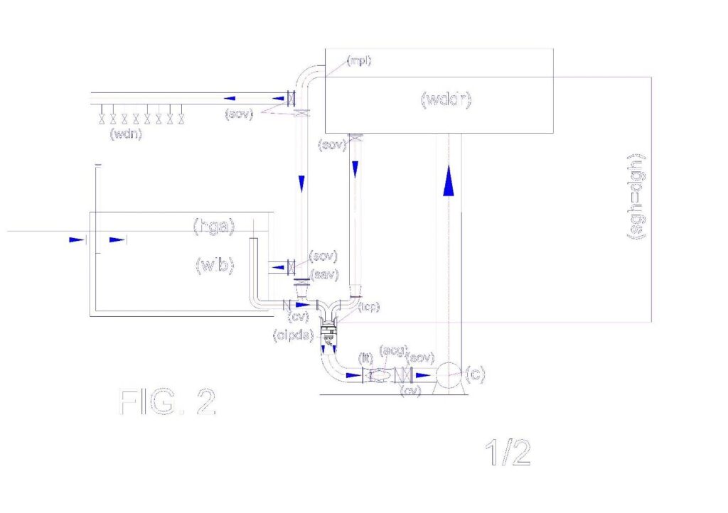
Legenda della Fig. 2: (C) collector; (oipds) overturned intubated pump with dual suction; (cv) check valve; (dgh) delivery geodetic height; (mpl) probe of the minimum or maximum level; (sav) supply additional valve; (sacg) submersible alternating current generator; (sacm) submersible alternating current motor; (sgh) suction geodetic height; (sov) shut-off valve; (tcp) tube containing the pump; (wdn) water distribution network; (wddr) water distribution and disconnection reservoir; (wlb) water lifting basin.
Fig. 1 illustrates how is designed an autoclave system for water pumping, hydro power producer, which reports the following legend:
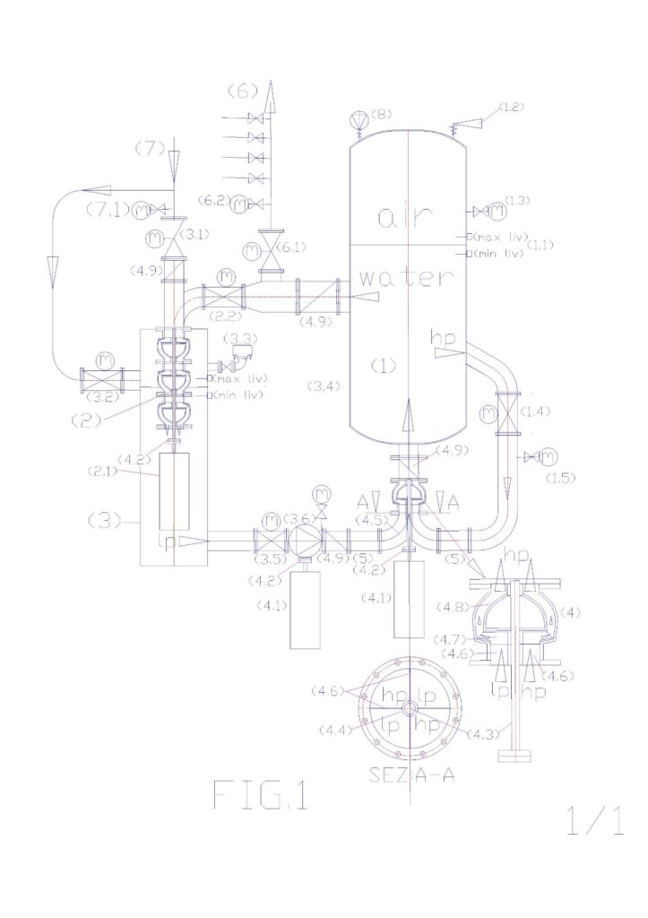
Legend: (1) autoclave pressurized tank; (1.1) level regulator with capacitive probes; (1.2) safety valve; (1.3) manometer with shut-off valve; (1.4) motorized valve flow control with position transmitter; (1.5) pressure flow transmitter; (2) pump used as a turbine (pat); (2.1) alternating current generator submersible; (2.2) motorized valve to supply turbine with flow adjustment; (3) water transit tank at atmospheric pressure and containment pat; (3.1) motorized valve to feed pressurized water network; (3.2) motorized valve bypass supply at low pressure; (3.3) air valves; (3.4) Water level control with capacitance probes; (3.5) motorized valve for water supply at low pressure; (3.6) feed electric pump in low pressure variable speed, driven by an inverter (4) electric dual supply pump on the suction side; (4.1) pump drive motor, with variable speed, controlled by an inverter; (4.2) joint pump motor coupling; (4.3) transmission shaft; (4.4) tube for protection of transmission shaft; (4.5) double curve with septa crossed separators in low pressure (LP) and high pressure (hp); (4.6) septa to flow separators; 4.7 closed impeller; (4.8) pump diffusor; (4.9) check valve. (5) flow diverter stub pipe; (6) water distribution network; (6.1) motorized valve to feed water distribution network; (6.2) pressure flow transmitter; (7) water supply line; (7.1) pressure flow transmitter; (8) electrocompressor.
As can be noted from Fig. 1, the autoclave pressurized tank (1) is fed with water coming from the tank (3), which is supplied from the water supply mains (7) and with the recycled water from the same autoclave tank (1). Contrary to existing autoclave systems, in this system, the pumps and turbines are always in operation and are the valves to divert the flow where it is needed. If the water distribution network (6) requires water, it gradually opens the valve (6.1) in function of the milliamps signal of a flow rate or pressure transmitter (6.2), in fact, the automation can be achieved in both ways: if there is a drop in pressure or the detection of a flow rate, we have to increase the degree of the valve opening (6.1) until the pressure or the flow rate stabilizes. When the pressure in the network rises to the nominal level or the flow stops for the closing of the network valves, the valve (6.1) closes. With the valve (6.1) closed the entire flow of water circulating in the system is diverted, by the valve (2.2) into the turbine or pump used as turbine (pat) (2), shown in the figure, which discharges the water in an open tank equipped with air vents (3), which, in turn, by means of a valve (3.5) and a circulation pump at low pressure, feeds a mouth of a pump with a double feed (4), while the second mouth is directly fed with the maximum pressure of the pressurized tank (1). The pressurization with compressed air is supplied from the compressor (8). Since the flow variable, the valves can be partially opened, so the water circulates where you experience the pressure drop compared to the nominal values, detected by flow rate or pressure transmitters located near the valves themselves. When there is taking of water from the network (6) there is a drop in pressure in the tank (1), which is immediately restored both through the initial operation of the compressor (8), both allowing water into the supply circuit of the tank (3) from the public supply network (7). This supply can take place through the supply valve (3.1) if the valve (2.2) is closed, or through the valve (3.2), if the 2.2 is partially open. The power supply is stopped when the electronic control controller (3.4) indicates the maximum level in the tank (3).
Obviously, this system produces the maximum electrical energy when there is no withdrawal from the water supply (6), for example, in the night hours. In fact, in such conditions, it produces energy without consuming the water that circulates between the two tanks. Consequently, does not consume even the compressed air, apart from that which is liberated into the atmosphere when the water is vented to atmospheric pressure in the tank (3), but this phenomenon is quantifiable as milligrams of gas per liter of water (nitrogen , oxygen, CO2) according to Dalton’s law of which is provided below the main formulas that explain the concepts, without considering the merits of the calculations:
In fact, in a mixture of ideal gases contained in a volume V and the temperature T, the molecules of each gas molecules behave independently from the other gases; as a consequence of this is that the pressure exerted by the gaseous mixture on the walls of the container and on the water surface is given by: where, R is a constant that that is 0,0821;
, … represent the number of moles of each component of the mixture. This law is valid under the conditions by which it is valid the ideal gas law is approximated at moderate pressures, but becomes more and more accurate as the pressure is lowered. By defining the molar fraction as the ratio between the number of moles of the ith component and the number
Total of moles present:
It is obtained that in a mixture of ideal gases, the partial pressure of each component is given by the total pressure multiplied by the mole fraction of that component:
.
In essence, for each gas present in the air is possible to calculate what percentage is solubilized in water at the working pressure, but for practical purposes, the energy that will spend to compress the air will be a small expense, since the air compressed, not ever coming out from the volume of the tank (1) has only small pressure fluctuations, and once it reached the saturation point not dissolves more air. One that is consumed is due to the lower water solubilisation of the gas, at atmospheric pressure. In fact, when the water passes through the tank (3), provided with air vents, releases a small portion of air, which becomes insoluble to the atmospheric pressure, which comes through the vent (3.3). But, obviously, the transit times in this tank are very narrow and the complete air expulsion process can not occur, because, immediately go back into the water tank (1) where the gas can not escape from the surface of ‘water, returning again to the maximum solubilization conditions.
Therefore, as mentioned in the introduction, a pressurized circuit with autoclave (1), coupled to a turbine (2), to an open water transit tank (3), to a water recycling pump with double feed ( 4), can operate in a very similar way to a circuit in an open vessel kept constantly full, shown in Fig. 2, even if it uses some different physical principles. In fact, in both circuits we can produce energy also lifting the water, provided that the water to be lifted are inserted in the recycling loop, always full, of the basin provided with a top hydrostatic pressure, entering from a suction inlet of a pump with a double feed. In fact, in this case, in the circuit in the open vessel the water comes out raised to overflow from the upper basin spending only the energy for the recycling, no lifting of about twice the maximum flow rate which can go out of the weir. The same thing can be said with the autoclave with pressurized circuit, even if the water levels to maintain constants are two: one in the autoclave tank (1.1) and one in the transit water tank at atmospheric pressure (3.4). Obviously, in order to constantly maintain these levels in the autoclave with pressurized circuit you are required a computerized management of the degree of opening of the motorized valves (1.4 – 6.1 – 3.1 – 2.2 – 3.1 – 3.2 – 3.5), the adjustment of the speed of the motors (4.1) of circulation pumps with single and double power, and, if necessary, also the commissioning of the compressor (8). But the complexity of the circuit is largely compensated by the energy from the energy saving and production that we obtain by means of this special hydraulic circuit, which is not against the principles of conservation of energy, but enhances them, exploiting synergies between the same, together with the compressibility of the air and the not compressibility of water. However, the heart of the system is the pump with double feed (4), without which it would be possible to circumvent the force of gravity in an open vessel (Fig 2) and the pressure of the autoclave (1) of Figure1. But it is also important to the way in which it feeds the pump that has to start from a certain distance from the pump, so that in the inlet section of the pump represented by the section A-A of Fig. 1, we have four separate streams of which two high pressure (hp ) and two low-pressure (lp), arranged diagonally to balance the hydraulic pressures in the impeller and the bearings. In order that this separation of the flows can take place it is necessary to start from the flow diverting (5) logs in that the double curve with separator baffles (4.5), must already receive the stream channeled into the correct position, so that it may cross as shown in section. A-A. Then, the half of the particular curves (4.5) using only half of the passage section, already arranged diagonally, that flow in only one input section of the pump already divided into four sectors seamless up to the fins of the impeller. In fact, with this type of supply, when the impeller is rotating, receives in the same quarter section, flows of water with the alternating sequence hp – lp, using the water thrust with higher pressure (hp) to push forward, the water with less pressure (lp). On the other hand this hydraulic principle is already used in multicellular pumps, where the water retains its total dynamic pressure (flow rate * unit pressure * the passage section), and increases from stage to stage, entering the center of the impeller , exiting at the periphery of the same, and returning to the center of the next stage, to effect, in particular, of the strength of the total dynamic pressure that follows the path of the impeller blades (4.7) and the diffuser of the pump body (4.8), as shown, with arrows, in the enlarged detail of the pump (4). In particular, to generate energy, from static water in the open tank or closed and pressurized, it is necessary intubation of the flow and pressure in a section of a one-way flow passage, without solution of continuity with the profile of the impeller blades. With the increase of the working pressures it is also important to the accuracy of machining, which prevent leakage in the reverse direction to the flow. In fact, the multi-stage pumps also reach operating pressures in unique sense of hundred bars.
As is known, the applications of hydraulic lifting pumps are endless. Sometimes you need very large flow rates with very small heads, for the defense of the territory and at times very small flow rates with high prevalence, for the most distant lifting from the water supply source. This resulted in a remarkable variety of pumps and impellers, which are produced throughout the world, being the lifting of water, along with transport, the largest energy expenditure of the planet Earth. Unfortunately, much of this growth is due mainly to the absence of the reflection that led to the conception of the pump with double feed that primarily uses the gravitational force, the principle of communicating vessels, the principle of Pascal, the Torricelli’s theory, instead of engine power coupled to the pumps. In fact, the pumps have been designed to overcome the forces that oppose the circulation of the water, independently of the energy required. Today it is no problem to build engines with a power exceeding 3000 kW, powered by 6,000 or 9,000 volts, to be coupled to the pumps. Today, large pumps, large motors, large turbines, are a credit technology, while large water projects with large dams are a credit to the construction engineering. It ‘difficult for the experts admit that this type of development has been wrong from the ground because the pumps would have to be designed to get the forces that oppose the lifting of the water, as indeed, was the case in mechanical lifts. In fact no one raises mechanical lifting weights directly, but does so through many systems that reduce the effort (inclined planes, rolling friction, reports belt drive, gear, etc.). Queste sono le ragioni fondamentali per le quali il sottoscritto ha studiato soluzioni idrauliche alternative per risparmiare energia. E’ stata una sorpresa, per lo stesso sottoscritto, scoprire che questi impianti si possono trasformare da grandi assorbitori di energia in produttori di energia, per la differenza tra l’energia spesa è quella prodotta, inserendo in tutti gli impianti delle turbine idrauliche. In all cases the pump is indispensable with the dual feeding on the suction side, which shows, through one of the mouths, at the entrance of impeller, the maximum dynamic pressure of the circuit, so that, as in the case of the last stage of a multi-cellular pump , the impeller must only provide a small part of the energy to ensure the continuity of the flow, and allow the feeding of the turbine with the maximum pressure allowed by the open system or with pressurized autoclave. In any case the exit of the turbine, if there is kinetic energy, the only opposition to the water circulation is calculated in proportion to the output speed (V2 / 2g), since the static pressure of the pressurized reservoir or tank do not oppose to internal circulations of the stored volume of water. La pompa con doppia alimentazione sul lato aspirante, serve soprattutto a miscelare due flussi con portate simili ma pressioni diverse, affinché la pressione maggiore si possa espandere nell’intera sezione di passaggio, la quale, ovviamente, deve essere almeno il doppio, di quella in ingresso, delle singole sezioni, se si vuole trasmettere l’intera pressione al doppio della portata.
At the current state of the doubling of the flow rate in a pressurized system it can only be done by inserting in parallel two electric pump with the same characteristics. But in this way they will also double the energy consumption. With the invention of the pumps with double feed and relative power supply circuit, making out the water raised by the overflow of the installations and reintegrating the same amount from the suction side of the pump, the plants behave as recycling plants in a vase filled always open , or in recycling circuits pressurized with autoclave. Therefore, the energy required for lifting is not that of current systems, but the one calculated by using the load losses without lifting water, which is usually hundreds of times lower. Suffice it to say that a piping DN 1000 with a flow rate of 1000 L / s, a water velocity of 1.27 m / s according to the tables calculated with the formula of Bazin-Fantoli has a load loss of only 1.5 m / km. Therefore, with the energy spent to lift of 1.5 m, 1000 L / s, we can move the same flow rate to a kilometer of distance in the horizontal, which is equivalent to the equivalent length of a recycling circuit much more complex than those shown in Fig. 1 and 2. Therefore, it pays to double the flow and producing plants always full of water, open or pressurized with pumps with dual supply, even without any energy production, but more so, the solution is not to call into question if ‘ plant can become a producer and not consumers of energy.
From the above description, it should be evident that the pumps must adapt to installations that serve from an environmental and energy point of view, while today plants are adapted to the performance of the pumps, which, despite being much improved yields and for performance, they may not exceed the original vices, which have not probed the possibility of circumventing the gravitational force, in open circuits or pressure with autoclaves, with this simple modification, which starts from the outside of the pump and can not not work. You just have to experience the performance for various types of impellers and the full range of pressures because the applications are endless.
For the construction characteristics of a pump with a double feed on the suction side, it is necessary that both feeding mouths are equipped with a positive hydrostatic head. Therefore in the case of small plants, with little geodesic inlet height, as in Fig. 1 has been provided an additional pump with single supply (3.6), which slightly increases the dynamic pressure on the pump suction dual fuel (4) , with the same flow rate, synchronized with the same, by means of an inverter connected to the drive motor (4.1). As seen in the diagram, Fig. 1, all the water that does not go towards the distribution network (6) passes through the turbine (2) producing energy, without leaving the plant. In fact, the momentary output of the water at atmospheric pressure is needed to produce kinetic energy into energy of compressed air pressure at the expense turbine, in the same way in which in Open vessel circuits produces energy by exploiting the high position of the waters of surface. But since the same amount of water, by means of pumps (3.6) and (4), the control valves, of the level reintegration and the automatism of the control system, immediately comes back into the tank (1) without to do expand the pillow of air and lower the pressure, this plant continues the energy production even during the feeding phase of the water network (6), in the same way in which the diagram of Fig. 2, feeds for overflow the water network to gravity. Infatti, nell’impianto autoclave produttore di energia, il contemporaneo mantenimento costante dei livelli dei due serbatoi (1 e 3), non comporta sollevamenti idraulici, ma solo circolazioni, pur assicurando la pressione di esercizio dell’autoclave. Obviously, if you exceed the capacities for which the plant was designed and levels (1.1 and 3.4) are not maintained, the pumps (3.6 and 4) must increase the number of revolutions and the compressor must compress the air that is expanded, so it is restored the rated operating conditions, that a properly designed system allows a low consumption and high energy production.
Without the exploitation of these natural energies (gravitational force and compressed air) and without the technical features, which are not few, considering that in one hundred and fifty years of industrial development, these innovations were never realized. In fact, these innovations to be efficient must take place simultaneously. It is not sufficient to put under the head of a pump without intubate from the surface to produce the dynamic pressure, as it is not sufficient to separate the flows of a pump with a double power if you do not enter into the pump body, touching the vanes of the impeller, also can not be put the pumps in parallel, as in the traditional lifting systems, but will need to place in parallel the complete plants, as represented in the diagrams of figures 1 and 2, since they do not exploit the static energy but that dynamic individually produced by the same plants, drawing from external sources, which in the case of Fig. 1 are the public water supply (7) and the atmospheric air that is compressed by the compressor (8), while in the case of Fig. 2, the external sources are the hydrostatic levels of the basins always full (wddr) and (wdn) and the gravitational force. It may seem strange, but even the pumps and turbines have never been put in series in the same facilities, since no one has thought that in the same volume of water you can use different hydraulic regimes in the descent phase of water to produce energy by means of the turbines, which discharge at atmospheric pressure (also under the head), while the water ski in a full basin is always a simple pressure drop at the outlet, regardless of the hydrostatic head or pressure of the air cushion. All these innovations have never been put together because the state of art has stopped at the pumps that raise the water against the gravitational force and the turbines that produce energy using the hydraulic jump, in which coincides simultaneously the drop of static and dynamic pressure. The experts have not considered that contemporary fall of static and dynamic pressure occurs in special cases that have already been exploited almost everyone on the planet Earth, even implementing large hydraulic works, with dams and reservoirs.
Today we must begin to take advantage of the normal cases of hydropower where the hydraulic jump does not exist but there are simple volumes of static water to be exploited as in Fig. 2, both for defense against flooding territory and to undertake large retail networks water at low pressure, which does not drive out the waters for losses due mainly to the high operating pressures and produce energy instead of consuming it; while for smaller and heights networks, serve the autoclave hydroelectric plants of Fig. 1, which also produce energy, eliminating even the unsteady flow disturbances with the aria pillows of autoclaves, but above all, producing energy, carrying out public services of primary and vital importance with investment and operating costs that are not comparable to any existing energy, including coal, which is the cheapest energy but also the most polluting.
If the authorities and the experts do not feel the need to modify plants, sensing that, through the use of the energy of the water position is possible to produce hydroelectric power, it can not be born a solution that provides the surface water intubation, even the combination of pumps and turbines to win the state of initial inertia and therefore no need to include in thecircuit the dual supply pump. In fact, only after having established the state of the art above mentioned it is also possible to consider the energy state of the art of the pressurized systems. But, as mentioned, in this case, design errors have become endemic, as well as hydro power is based on a particular case, that the experts have transformed into a universal event. In fact, the big water projects with large reservoirs and dams, necessary to produce hydroelectric energy, become absurd if it is proved that we can produce the hydropower throughout with simple hydraulic systems.
The famous experiment of Pascal, has shown that in a closed tank the hydrostatic pressure expands in all directions. Just even a small tube for smashing a wooden barrel. But to produce electrical energy is needed the dynamic pressure which ensures the exercise in time on the poles of a turbine. This application requires adequate passage sections and the continuity of the flow, which in small volumes of water can be secure only if it does not disperse the water and exploit advantageous hydraulic schemes in the energy production phase (water drop or pressure drop ) and thrifty energy regimes in the phase of recovery of the water, without charge for lifting water. In these systems the dynamic pressure is equal to the unit pressure for the passage section for the flow of water, therefore the pump with dual supply must be dimensioned for the sum of the two flow and with a delivery passage of a large section, which returns to autoclave, as in Fig.1. In fact, in this circuit on the pump delivery should not win the external resistors to the recycling circuit, as the pressure of the compressed air cushion. The water circulation occurs within the stored volume of water with a very small head of the pump. But the body of the pump has to withstand high hydrostatic pressure, otherwise it falls apart as the barrel of Pascal.
Therefore, suppose to realize a small condominium plant that produces energy by means of a submersible AC generator (2.1) coupled to a pump used as a turbine (pat), which exploits the useful height Hu = 35 m and an electric pump with dual supply DN 150 with a capacity of 35 L / s. Assuming the turbine efficiency is 0.75, by applying the formula Pu = η*1000*Q*Hu/102, we have an energy production 9,0 Kw (0,75 * 1000 *0,035 * 35 / 102). Assigning to the pump a prevalence of 0.4 m and a yield 0,6, the power absorbed by the same, which leads a double flow of that which passes into the turbine, calculated by the formula 0,4 * 1000 * 0,070 / 102 * 0,6 = 0, 0456 KW. While the additional circulation pump (3.6), with a flow rate equal to half, suppository with the same yield and prevalence absorbs half of the energy calculated for the double feed pump (0,0228 Kw). In this case the ratio between the energy expenditure and yield is 131,38 (9,00 / 0, 0685). In fact, the load losses in the descent tube, in the turbine, the special pieces and losses at the outlet, are all absorbed by the dynamic pressure on the pump suction, while in discharge have no appreciable load losses, not exceeding the level of ‘water (which is incompressible). No wonder with this result, Whereas it compressed gases are accumulators most powerful energy, flexible and economical of electrical energy storage.
But the plant surprises compared to current solutions for lifting and water distribution are not yet completed as the solutions of Fig. 1 and 2, which do not exist today for amazing scientific, technical oversight, policies and economic, at international level, can be strung together, as shown in Fig. 3. In this figure, for example, the distribution of water of a city or district can diversify the operating pressure using the water distribution by gravity in areas close to the main tank (wddr), while the more distant areas or which feed the highest neighborhoods can be pressurized with air cushions of diversified, without varying the prevalence of the pumps and therefore the power absorbed by the motors, always preserving the ability to produce energy with the water recycling in the individual installations, both at the level of district distribution, that condominium. The computerized management of hydrostatic levels of open tanks, pressurized and valves and a pump speed variable motors can allow very large energy savings and very large energy production, today, unsuspected at state of the art, but easily achievable because the technologies are all existing. Missing only minor modification power of the pumps and the turbines. In fact, even the turbines, as seen in the diagram, can be supplied with different pressures channeled flows ranging up to the blades of the first impeller, which sum the flow rates with maximum dynamic pressure in respect of the principle of Pascal.
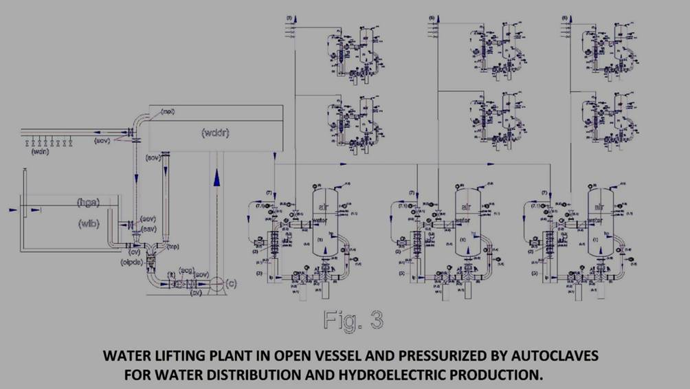
The last things to consider are the following:
If to the autoclave systems, power producers we subtract the water distribution network (6), the supply (7) with valves 3.1 and 3.2, we find that not only simplifies the system, but that, even these systems can also be used to produce mobile power, by recycle of the water contained in the autoclave tank, obviously, not on small means of transport, but on those of larger dimensions, since the fairly bulky of autoclaves. But this is a subsequent speech in this application, which can be achieved by pushing to the maximum operating pressure, eventually, using gas even more compressible of air. After all current heat engines have reached its present level of technology after one hundred and twenty years of designs, billions in investment and thousands of patents which was attended worldwide, without solving the original defect in CO2 emissions and particulate matter. If there is a real will to solve environmental problems, the effort that has been done to improve the thermal energy, should also be done by investing in the proposed system, which is much more complete, clean and cheap. In a few years, we will be able to increase the operating pressure and reducing the overall dimensions of the autoclaves. Certainly we can replace a large part of internal combustion engines in circulation on transportation, either by solving the economic problems for the supply of fuels, and environmental ones, due to CO2 emissions and particulate matter. For example, the energy plant condominium calculation with a flow rate of 35 L / s water and a pressure of 3.5 bar, which produces 9 kW / h of power, if we increase the pressure to 35 bar, would produce 90 KW/h; but if we also bring the flow rate to 350 L / sec, it would produce 900 KW / h. Obviously, we are at year zero in this direction, but only because the reflections on this way of producing energy arriving very late and all the experts, public and private, have focused on other energies, which, unfortunately, have already shown to be less efficient, but also less useful, since not to combine with public services of primary importance, such as the distribution of water, the depuration, the dissalazioni, transport without pollution. In the latter case, fortunately, today there are the technologies for feed in the initial phase the pump motors and valves with three-phase UPS. After the start of the system, managing the flow of water with control valves and the speed of the pumps with inverter, we can produce the mobile energy in large quantities, replacing thermal engines and also making unnecessary the distribution networks which, not only require large investments, but also involve security issues and management, and disperse enormous amounts of energy in the air or underground path.
GENERAL CONCLUSIONS
The sustainable future of the environment and energy is not possible without scientific organization of work in the environment and energy sector, but this organization can not be achieved by relying solely to market forces, as was the case with ‘ scientific organization of industrial labor. The laws of environmental and energy do not allow planning and management errors. There is only one way to purify the air, desalinate and purify water, which is the global one. In the sense that all organic and inorganic cycles involved must be closed in anthropogenic systems. In fact, all the cycles that are not closed are transformed into global pollution and cannot be completed. Since the parameters to control are many and can not be controlled with a single process, the implants must be connected together, regardless of the technology used. This is the reason why in SPAWHE speaking of synergies and global systems.
However, in 2016, yet there is no environmental system, public or private, that meets those requirements. For about ten years the inventor of SPAWHE tried to retrace the purification of water and air processes, proposing, of fact, the scientific organization of environmental work in the same way in which Frederick Taylor did, back in 1911 for the industrial sector. Unfortunately, this type of organization can not be born without a new strategic inventions that serve to rationalize some disciplines and as a link between them, such as those described in this publication.
The mere fact that no international organization has felt the need to organize such work after more than a century of success in the industrial Taylorism, shows that the current world-class executive is not up to address global environmental and economic problems. When we talk about ruling class should not only refer to politicians but to all the leaders in all sectors, to those who inform, those who teach and also to religious orders. Do not they know the leaders in its sector that is fundamental organization of work? They do not know that in their specific field upgrading of the state is almost daily? they do not know that many innovations that improve a sector from other sectors? The relevant leaders seek possible synergies and apply to theyr sector with appropriate adaptations.
The question that arises SPAWHE is as follows:
If all of them are specialized in individual sectors and individual geographic areas, global sector who manages it? If the individual sectors will enhance each other by exchanging, copying or stealing inventions, who improves the overall sector? The answer is very simple: None. SPAWN has shown that to comprehensively improve the environment and the economy is not enough that human activities are improved technologically individually. Must be changed the way we design because to complete all organic and inorganic cycles left pending of human activity, all the activities in one way or another, have to be connected through the purification systems, which may not be the current ones. Changing purification systems, inevitably, will also change, energy. But who should make these changes unless are put together technical groups with different experiences? Not only it was not done this thing logic. But even spawhe that has tried, is ignored by all stakeholders. Above all, by the environmental authorities and economic development, Italian, European and international. One wonders who are the more than 7,500 visitors https://www.spawhe.eu. Are friends or enemies of the environment and labor? If the illustrated projects, until now, have not found counterparts, will must think that visitors are more enemies than friends of SPAWHE. This is not due to the non-sharing of projects but simple partisan interests. The individual sectors can certainly not go against their interests, financing and participating in the implementation of global solutions, which dissatisfy everyone, even the chosen technologies, that enter in global system. Infact, the global systems are designed differently from those local. By SPAWHE, you can produce biological energy purifying together water and air, as described in https://www.spawhe.eu/the-role-of-biological-energy/. But today the biological energy is content to be, at best neutral, emitting organic CO2 into the atmosphere instead of the fossil. Why manufacturers of such energy should produce alkaline water by reacting CO2 with calcareous material and cooling water or sewage, if the law does not require to go beyond the simple objective to produce biological energy? The global public entities may not delegate to private energies that interact with the environment, unless they legislate in minute detail the energy production cycles, including all parameters, even, the amount of CO2 emitted in atmosphere, whether fossil or biological. If producing biological energy we can reduce the amount of CO2 in the atmosphere, why to be content of neutrality of energy and do not try to resets the percentage of CO2 of the days before the industrial era?
While hydropower discourse is entirely different. It was traded the particular case of energy with the hydraulic jump, as a universal law, and has escaped the general case which would produce hydroelectric energy even in an apartment building using the energy of water located on the surface in the same volume of water. This energy that the experts refuse to experiment with stubborn silence, probably, is the cheapest energy in the world. It cost very little both in terms of initial investment (having no need of dams and basins), both in terms of management (pumps and turbines are very simple machines), both in terms of production costs, since in circuits always filled the raw material is the water that is not consumed. But it can produce energy even bringing oxygen in polluted waters, recycling, raising and distributing water, as described in https://www.spawhe.eu/from-efficient-purification-to-sustainable-energy/.
The energies that do not interact positively with the environment or are simply neutral, should be considered only if those who interact positively with the environment are not sufficient to produce the entire energy needs. Instead, in 2016, the predominant energies are those that pollute, those reserves are neutral ones (discontinuous with low yields and high disposal costs), while we have not those who interact positively with the environment, because the public and private organizations they pretend they do not exist and do not understand them. SPAWHE, without funds, could not help but hypothesize running its solutions and continue with a virtual advancement of state of the art. Which allows to see a very different society from the one in which is leading the current world-class executive, that led to the title of this article.
With this publication, SPAWHE asserts that it can produce energy even while we desalinate. sustainably, huge flows of water, which will also become natural fertilizer for places deserts hundreds of kilometers from the sea. In fact the sea water, deprived of excess salts is the richest element of minerals that can exist to produce vegetable substances. So, with the sustainable desalination deserts will become gardens, thanks also to what is described in Chapter 2, which allows the production of energy during transport the water. If all these things are true (and they are true), we should not fear the increase in world population to nine billion because we could feed as many as twenty billion people with the current resources. E’ necessario soltanto organizzare scientificamente e globalmente il lavoro secondo lo schema di SPAWHE.
It ‘must go from the scientific organization of industrial work called “Taylorism”, which does not cure the environmental and energy aspects, to the scientific organization of global labor, we can also call, “SPAWHISM” not linking this system to a person’s name, but to the selection of industrial systems, known environmental and energy, which are capable of interacting positively with the energy sources to increase along with the industrial productivity also environmental protection.
We do not need to cheat with GMOs and even worsen the quality of the meat we eat, forcing the animals to live in confined spaces without physical activity, fed with feed, chemical antibiotic substances that promote obesity, not the quality. It can produce energy by producing quality feed in the sea without imprisoning the fish by means of colonization of oceanic plane by means of unsinkable buoyancy systems, achievable with oil derivatives, as shown in chapter 3.
Why continue to use oil as a fuel, which is not only polluting but more expensive and less useful energy hydroelectric fixed and mobile? If we do not develop truly alternative energy and we continue to waste oil, as we realize the floating systems that will allow us to create nutrition and prosperity for future generations and to bring calcium to the surface in the ocean waters, which have already lost 30% alkalinity? Determining the real problem of global warming. We have to thank for these disasters the insiders public and private works of the past, but the current ones, are even worse, because despite having the sufficient technologies do not employ globally, to create profit instead of the common welfare.
If the silence continues on SPAWHE solutions, it is right to ask ourselves where the current class public and private leaders want to bring us? It is right to ask the reasons for which public bodies do not develop global projects involving energy production, as it is right to ask the reasons for which the medicinal products tested by the public research are produced by multinationals and not from public producers, which would the duty to produce them at an affordable cost. There is nothing clear in environmental management of energy and public health worldwide. We can not understand the line between good intentions, incompetence and hypocrisy among the millions of professionals, as in a dramatic novel by Franz Kafka. Unfortunately, this system, which applies only in small areas the industrial TAYLORISM, has expanded globally, and is able to waste resources even where there are optimal conditions for producing them. It is very far from the SPAWHISM that could be considered the expansion of Taylorism even in environmental and energy systems, not locally, but globally. But the way of SPAWHISM, is very difficult respect to the Taylorism because the innovations are obstructed by the corporations who want to continue to manage the environment with local and commercial solutions while public bodies do not even know the basics of industrial Taylorism to be taken as a model to scientifically organize the global enforcement of environmental protection and energy production, by selecting the technologies that are best suited to globalization.
The same intellectual property, tied to the number of patent applications, does not protect the inventors, but only those companies that can pay for protection. This will discourage large sustainable inventions and carry on only the business of multinationals. But SPAWHE, although virtually, has shown that in the environment, to be efficient, the plant must be global, consequently, little commercial. This means that intellectual property needs to be changed, giving priority to the common good, not only the commercial aspects of inventions. They do not serve the commercial products in the environment and energy. Multinationals must be confined to providing the main components, but systems must be assembled on site, if we want to achieve complete cycles, which are simultaneously energy and purifying water and air, without producing acidification in water and disperse heat and pollution unwanted in the air. That cannot happen with the current sewage systems, purification, commercial machines of conditioning and chimneys. SPAWHE showed how to realize the global urban systems. Combining multiple systems together will reduce the costs of investments, compared to separate systems, and create more wealth and more work. If the objectives were clear there would be no doubts about the solutions. But the face of these logical things demonstrated in all the ways in over thirty patent filings, reports and drawings, they erect tall and very solid rubber walls and silence, continuing to build plants without meaning. E ‘right to ask if they make real opposition those who organize marches and protest against pollution and global warming. I do not speak of the demonstrators, which are certainly in good faith. I speak of the organizers who should have technical and scientific knowledge higher than the marchers. It is possible that they even want to talk about global alternatives, based on the organization of scientific work? It is possible that they do not realize that not entering into the merits of the solutions and not making concrete choices and alternatives, they just ask for more money to be invested in existing solutions? At best demonstrate their expertise by choosing the lesser evil between coal, oil, gas, wind, solar. It is possible that even authority figures such as Al Gore and the entire staff of the scientists IPCC (Intergovenmental Panel on Climate Change), awarded with the Nobel Prize back in 2007, will continue to report problems, without going into the global scientific organization of environmental and energy work. It ‘possible that these important personages do not realize that individual environmental inventions are useless, including the C.C.S (carbon capture and storage), it seems that the largest project being carried out. Which does nothing that increase energy costs, but shifting the risk of disasters in the underground. SPAWHE would clean fossil energy in the limestone greenhouses using the CO2 in the environment, producing alkaline waters, but have even more important reserve solutions, such as hydroelectric, submerged, with water recycling and pressurized with compressed air for the media of transport. Produce energy producing facilities of defense of the territory, purifying water and air, desalination, transporting and distributing water, which also become fertilizers against deserts.
The story of SPAWHE seems a history of industrial espionage on the contrary, where companies, public and private, do not compete for stealing secrets and innovative ideas, but to ignore them. In part, because they highlight colossal purifying design errors and energy, in part because they show that with the technologies developed, adapted as appropriate, we could follow more sustainable patterns of development. Completely different from those on which they have invested and are investing, both of solving environmental problems as energy and food.
The world cannot be governed without coordinating the direction in which you need to develop science and technologies applied in the field. It is necessary to distinguish between scientific research, production of consumer goods trade and sustainable industrial design, covering all sectors. The unions that defend the workers of the industries know the organization of industrial work, because they do not understand that they have to beat for the global labor organization, based on the closure of global cycles, which is an extension of the industrial cycles over the perimeter of the manufacturing factories?
It does not take much to understand these concepts, that might seem utopian, if they were not also been developed solutions that intertwine and connect in SPAWHE website. Professionals, public and private, cannot continue to make industrial plants, purification, energy, urban, that disconnected from a global system, must necessarily produce and disseminate in the environment acidic water, CO2, SOx, NOx, particulates.
Renewable energies that have been chosen by experts do not interact with the management of production and water and air cycles involved in the processes, so they can not take advantage of the synergies, which would reduce the costs, as shown in the works of SPAWHE. Whose sustainability is based on global reasoning entering into the details even when designing local plants.
Who proposed SPAWHE, knows that it is very difficult to follow global arguments for a single person, but it is also equally difficult to put together people with different preparations to make common reasoning. Almost forty years of transversal work experience were required to do global reasoning and ten years to put on paper the solutions and arguments that determine a virtual advancement state of the art, based on non-implemented inventions on the modification of the purification plants, energy, lifting and distribution, and with this latest publication, including desalination, food and social. In all this time, despite the good developed technologies, environmental protection has not taken concrete steps forward, thus the birth of Spawhe and the spawhismo should have been welcomed with greater enthusiasm by the world’s environmental leaders. The spawhismo should be much more important of Taylorism because those who design environmental and energy systems that interact with the environment, cannot be separated from the social aspects involving such designs. They must provide for the possible damages, also designing the infrastructure necessary to neutralize them and imposing, through the legislature, how to design local systems to private designers. In 2016, it should have been clear to everyone that the global purification must begin locally and must never be interrupted moving water, muds and air from one facility to another.
Only through cross experience the single designer can understand the importance of this type of design. If the designer stops to develop only the details that are ordered, does not understand the importance of this work and do not notice inconsistencies, which in many cases frustrate the work done with dedication by thousands of people for the absence of a greater global vision. They cannot give any contribution even criticism from philosophers, writers, environmentalists, if they do not have the ability to offer a complete alternative design. Indeed, protests and criticisms, not accompanied by global alternative designs, do nothing more than increase the funds available to those who do not want to change anything and only aim to have more funds available.
Today we have the paradox that a small virtual invention of SPAWHE, the pump with double feed on the side suction, described on this and other publications would circumvent the gravitational force, completely changing the environmental and energy solutions, created by the advent of the time industrial. However, these pumps have not yet found partners involved in the trial, which costs only a few thousand euro. Second, the experts, public and private, who have wasted trillions of dollars by the advent of the industrial age, in unnecessary testing, we continue to waste energy even in future centuries, just because SPAWHE not have the money to build the simplest prototypes. It is not even served an open letter to Bill Gates that hopes in a miraculous energy, to find these funds. If there was one chance in a thousand that these pumps can operate, men should pray to the saints in heaven or their Gods, to hope that they work. In fact, it is the only chance we have to get around the force of gravity, making the plants exposed in this publication and change many other plants around the world that pollute and consume power, whereas they could produce it. Instead, the world ruling class does not want to know, and hides its head in the sand. SPAWHE is sure at 100% that is possible, but will not make debts to prove it. Continue to produce virtual inventions, considering operative these pumps. Sooner or later the truth will out, and the world of science and technology will include that have overlooked the elementary concepts to look the unsustainable, which led to starvation to wars, and almost destroyed the planet, while the sustainable has always been to hand.
Luigi Antonio Pezone.