Floating system with extruded polyethylene pipes, ribbed, reinforced and filled with polystyrene.
Italian patent N. 102016000058416 dated 07/06/2016
Abstract
The significant delay in the development of the exploitation of marine resources and the protection of global environment is due to many factors, among them the lack of economic floating systems and unsinkable. However, such systems could not be studied in detail without also provide technical solutions that can lead to colonization by mass of ocean flat. In fact, at present, it does not make sense this colonization, being inhospitable ocean flat for human life, both because water desalination is not sustainable, both because from the point of view of food, the ocean flat are not productive. The fish production is concentrated in areas close to the coast, where the wind and water currents allow the production of phytoplankton and zooplankton, and thus the production of food for the great variety of fish species and for men. However, the ocean flat could become the most rich source of human nutrition, because the invention of “Floating system, hydroelectric, desalter, extractor of calcium and carbon from marine deep water.” allow to desalinate, produce energy and abundance of fish at the same time, raising to the surface a part of the deep water, rich in calcium and carbon, dissolved by high hydrostatic pressures. These plants will produce phytoplankton, zooplankton and alkalinity, also fighting water acidification and global warming. In this project have been incorporated extruded ribbed polyethylene pipes, filled with polystyrene, to make unsinkable plants. Of course, it must also be made unsinkable floating islands and connecting roads that will serve around these plants. Therefore, even though the valid existing flotation systems used for the construction of marine shipyards, should give place to a large series productions that can be only realizing them by extrusion. Even sea transport of these tubes must be sustainable and economic, by assembling, in shipyards major floating structures and bulky and transporting them in place by tugboats.
Description
At the state of the art, although there are valid flotation technologies with modular elements in polyethylene coupled in a vertical and horizontal direction by means of profiles of galvanized or stainless steel, these modules, realized by molding, have a high cost of production. They can be used, as are, to realize houseboats, marine and lacustrine sites, temporary roads etc. But for a series of great use, such as that suggested for the realization of “Floating system, hydroelectric, desalter, extractor of calcium and carbon from marine deep water”. and the induced activity that will result, it is considered much more economic the following solution, that It estimates to raise the floating elements directly by extrusion, such as the current of polyethylene pipes, with the only difference that these pipes will be produced with perforated external ribs at regular steps, so that they can be coupled to each other and to the metal structures of containment or support , in the various possible compositions. Furthermore, inside the tubes can be inserted some radial ribs in tubular profiles, mounted on a central tubular axis, arranged in a regular step as a function of the immersion depth, certified with a specific report calculation on the resistance of the polyethylene and metal material. Finally, the tubes will be made unsinkable by means of the sintered polystyrene foam filling, which has a volumetric mass between 10 and 40 Kg / mc, and is then constituted by the average of 98% air and only 2% of pure structural material hydrocarbon. Therefore, any damage to a floating hose, would not cause the immediate filling with water and sinking, but would allow a large margin of time to repair the damage or replace the damaged pipe. Whereas the tubes obtained by extrusion products can be of any length, to save costs, it is not hazardous hypothesis to achieve the production facilities close to the sea, to assemble systems in adjacent coastal shipyards, tow them and transport them directly in the final working area, where it would be more difficult and expensive the assembly work, in general. But, above all, in the specific case of the “Floating system, hydroelectric, desalter, extractor of calcium and carbon from marine deep water”, because of the complexity and importance of the work to be performed, it is preferable that the site platform, as represented in the Fig. 1 is assembled in a shipyard with all mounting equipment mentioned in the legend (bridge cranes, hydraulic cylinders, working loft columns of electrical winches) and transported on site by a tugboat.
FIG.1
Fig. 1 shows the starting point, ie the float construction site from which arises a “fFloating system, hydroelectric, desalter, extractor of calcium and carbon from marine deep water”. This facility to extract the calcium and carbon dissolved from the high hydrostatic pressures in the deep water must come down over 4000 meters deep. Assuming to provide a system that goes down to 6000 meters, with steel pipes Dn 1400 from the mechanical strength point of view, the two parallel pipes for the 6 km long Dn 1400 that serve to implement the system may be of the API series 5LX, grade X 70 with a thickness of 10,31 mm, in steel with the following characteristics: Ks = 70.000 p.s.i = 49,2 Kg/mm2; Kr = 82.000 p.s.i. = 57,6 Kg/mm2. The marine water has density 1,025 kg/L therefore at 6.000 m di profondità exert a pressure on the seabed equal to 6150 m of water column (1,025*6000) = 615 Kg/cm2 = 6,15 kg mm2. Therefore, the stress that the water exerts on the piping material is much less than the minimum yield strength. This means that the pipes cannot be deformed if the pipes are full of water, while having minimum thickness. In fact, the problem to be solved are the stresses due to the weight. It is advisable to use high quality pipes with low thicknesses. The tube X 70 Dn 1400 taken into consideration it has the minimum thickness of the series (10.31) and weighs 358,73 kg/m, that increase of 15% to take account of the flanges, bracings, etc., the whole load becomes (12.000*358.7*1,15) equal to kg 4.950.474, subtracted of the upwards hydrostatic thrust, equal to (4.950.474*1,05/7,8) pari a 666.410 Kg, subtracted of the upwards hydrostatic thrust, equal to 92.096 mm2 (1.422,4*3.14*10,31*2) which would have a maximum stress in tubes placed at the top (that support the entire load) of 40,91 kg/mm2 (3.767.710/92.096).
There is no cranes in the world that can support the weight of nearly four million kg, therefore, to be able to build the facility which raises calcium and carbon from the deep waters is necessary to carry on a temporary construction site platform with the mounting equipment they serve to the laying of the pipes. At the center of this platform is accomplished the immersion hole (ih), of such dimensions as to contain the lifting cylinders (hc) with the useful travel of 6 m, which will be mounted on a bridge crane (bc) with three hoists, which serve for the mounting and the vertical transport of pipes 12 m long bars, the relative bearing structure (SSBC) with the frames in more supporting floors (tcswr). Each floor contains an electric winch with its rope (sr). So the tubes have dropped in deep sea while they are mounted and the final framework are supported simultaneously from above and from the four sides of the platform. The lateral suspension points increase as increases the depth of immersion, both to support the load, both to contain the lateral stress, due to ocean currents, both to contain the unitary tensile stress, due to the weight of the tubes. The flanges, visible from the drawings, will be welded because the bolt sections represent a weak point in the tensile strength. The flanges are of a special type, used as supporting bars for the descent of the pipes (dt-ut), to connect the bracing and the rope pull (sr). Whereas the linear meter weight of the pipes in the water with flanges and braces is estimated at about 314 kg (3767710/12000), each tube bar of 12 m, including accessories weighs approximately 3768 kg. Therefore, if we make a link to the platform every 60 m depth with ropes of 30 mm diameter, the total breaking load of 218,700 kg (3 x 72,900) we support the entire weight of 60 m (18,400 kg) with a safety factor of to 11.6 without regard to the load supported by the tube itself, which, as we have seen entail a tensile stress of 40.91 kg / mm2.
As seen from Fig. 1, the floating structure using a hydraulic system for the vertical movement of the column of tubes (dt) and (dp), consisting of two vertical hydraulic cylinders simple effect (hc) with a stroke of about 6 m, which by discharging the hydraulic oil in the tank of the hydraulic unit (othcu), lowering the cylinder rods and they lower the entire column of tubes as they are assembled and are mounted also the bracing with the aid of the bridge crane (bc) and the loft (ls). The pipelines will be pre-assembled at the factory with the support flanges of 12 m elements, painted with epoxy resin cycles inside and outside, leaving only the edges to be welded in place unpainted to be painted on site with the same cycle. The braces will be hot dip galvanized. The decline of the pipes will be assembled by placing the column on the brackets (hcb) mounted on the frame (sf) located across the diving hole (ih). The frame (sf) is driven by hydraulic cylinders (hc) embedded in the structure of the dive hole (hi). The brackets (hcb) are dimensioned for the entire load-carrying (3,767,710 kg). Assuming to work with a pressure of 250 bar to support all loads during assembly. The section of each cylinder will be approximately 7535 cm2 (3,767,710 / 2 * 250), which corresponds to an internal diameter of 98 cm. A bridge crane with three hoists with capacity suitable for the lifting of feeding tubes and bracing elements to assemble and fall into the sea with the help of a mezzanine (ls) that allows you to work on two levels. To reduce the stress due to the weight of the pipes estimated above, three cables have been provided (sr), (already mentioned above) that connect the individual bars of the tubes to the floating platform (sbp). These ropes (sr) from the winches contained in the multi-storey frames (tcpwr) arranged on the outer perimeter of the upper floating platform, roam the property and enter into the dive hole (ih) and lugs with snap hooks are superimposed on the perimeter of the hole of’ immersion on corresponding six pegs, according to the dive order which must have in the descent of the pipes. In fact, every sixty meters (equal to 5 bars of pipes), six strings will snap to ribbed flanges, three for each tube, while the inner side will be connected with the braces (br). Therefore, we will have n. 600 workstations of winches (6000/60 * 6) 150 arranged on each side of the platform (sbp) with the lugs already brought close to the diving pit. Not being able to wrap the whole rope on a winch only, each frame (tcpwr) brings more superimposed winches. When it runs out the rope of a winch is released and attached to the winch with junction elements of the lower floor, until the entire frame it runs out and is replaced. The strings that start from periphery of the platform (mftp -sdp) not only serve to lighten the axial traction of the tubes but also for bracing the entire column in all directions. Obviously, even the naval type anchors (na) can be dropped with stations of winches (tvpwr) located at the periphery of the floating structure. when Assembly is completed it will support the load with a fixed clamp brackets (cb) on the structure (for this purpose the last bar of piping will be flanged with a sufficient amount of bolts) and will be fixed stably across the terminals of the 600 positions of winches on the periphery of the structure. After the laying of the pipes that come down in the sea bed are fixed permanently on the metallic structure of the platform, after disassembling all of construction equipment, in place of which it is mounted the desalination plant.
Legend of Fig.1: (apos) abyssal plain ocean seabed; (bc) bridge crane; (bcb) bracket cross bracing; (br) bracing; (cb) clamp brackets; (dt) descent tube; (f) filter; (fsp) flange for support pipe; (hc) hydraulic cylinder; (hcb) hydraulic clamp brackets; (hcbf) hydraulic clamp brackets fixed on supporting base platform; (ih) immersion hole; (itia) intubate turbine with incorporate alternator; (ls) loft in steel; (mftp) modular floating tube made in polyethylene; (na) navy anchor; (osip) overturned submergible intubated pump; (othcu) oil tank and hydraulic control unit; (sbp) supporting base platform; (sfep) special flanged end pieces; (ssbc) support structure bridge crane; (tvdwi) throttling venturi deep water intake; (tcpwr) transportable chassis with many electric winches for the descent of the ropes; (ut) uphill tube; (wl) water level.
Although calculating accurately the weights of the tubes to be supported and the system of final desalting, the immersion of the final framework platform is only ascertains the end of the assembly of all the suspended tubes which descend in the ocean depths, after disassembly of the equipment construction and mounting them in place of the desalination plant. To achieve the final structure of the platform floating floor, a percentage of floating tubes seats above will be filled with compressed air at the maximum expected operating pressure of the dive. At the end of the work, by means of a threaded connection, with by-pass valve, the air may be replaced with water, if the platform has to soak in the water more. If the platform must climb must be added to the structure other floating modular elements.
We do not enter into the merits of the tube manufacturing process but simply identify the production technology, because, extrusion occupies a prominent position for versatility and breadth of application. The extrusion technology is an operation that operates continuously and in stationary conditions to produce different kinds of artifacts characterized by symmetrical or asymmetrical sections that are repeated identically along the extrusion axis. In its essential lines, the production of a polyethylene pipe is very simple. A production line of a polyethylene tube is constituted by a loading hopper of the polymeric material granules which feeds an extruder, which is constituted by a screw pump which rotates, with very precise coupling, inside a heated cylinder. Between the cylinder and the screw core is located in the molten material to be extruded, which is then forced through an extrusion head. The molten material rotates at a lower speed than the screw, and then is pushed forward from the crests of the threads of the screw and is then forced through an extrusion head. Having planned to accomplish a tube with perforated ribs which serve for reinforcement of the tube and for the fittings, the holes must be made by means of a punching the top of the entry into the extrusion head, when the material is still plastic, in sync with an eventual slowing of the speed of advance of the material in the extrusion head. It does not matter if for processing requirements will produce the punching of the slots instead of holes. The function that must carry out the holes or the slots is identical.
Below the main features of a low and high density polyethylene pipe ( LDPE) (HDPE)
Specific gravity at 23 degrees C. (g/ cm3) 0,917 – 0,925 0,95 – 0,96
Melting point crystallographic (oC) 105 – 115 125 – 135
Tensile strength (kg /cm2) 80 – 170 250 -350
Elongation at break (%) 400 – 650 100 – 300
flexural rigidity (kg / cm2) 800 – 900 9.000 – 12.000
Considering that polyethylene pipes for floating shall be of a size large enough to perform their function may also be used, in part, as the descent and ascent of the water pipes that extract the calcium and carbon from the ocean depths. In fact, if we compare the breaking strength between the pipe (HDPE) of 250 kg / cm2 = 2.5 kg / mm2 compared to steel Bees 5LX which has a breaking load of 57.6 Kg / mm2, we can say that the ‘steel is twenty-three times more resistant high density polyethylene, but considering that the polyethylene pipes are produced with thicknesses at least four times higher than those of steel, we can say that the difference in resistance is reduced to about 5.75 times.
But whereas the static stress may also be doubled in the steel without serious problems, we can say with certainty, that a third of the way into the depths of 6000 m provided the example of installation concerned, you can achieve with HDPE pipes, lightening the load to be supported by a third, being the pipes HDPE lighter than water.
Moreover, whereas the polyethylene is a synthetic polymer based on carbon is not recommended for use with the high pressures that might lead to phenomena of dissolution of the synthesized molecule. In case of use of HDPE pipes as descent and ascent in the tubes of calcium and carbon extraction systems by ocean depth, the transition from steel to polyethylene is realized by means of flanged coupling and all the axial load due to the weight of the pipes in underlying steel must be supported by the platform peripheral winches (tcswr) not by the central hydraulic cylinders (hc), even during the assembly phase. The strong ribs of the tubes, designed for mounting of the floating solutions will also be useful for this use, both for the support, both for the lateral stiffening. For the use of the tubes as floating, he was expected the internal reinforcement of the same by means of a radial pattern of structural steel, with six rays, coinciding with external ribs, where they will be applied loads and mechanical linkages. La raggiera sarà montata e fissata su un asse tubolare e fissata con viti a mordente sullo stesso, mentre la parte periferica dei raggi è tenuta insieme da una fascia di lamiera calandrata. Nella Fig. 2 si riporta la sezione tipo di un tubo di galleggiamento.
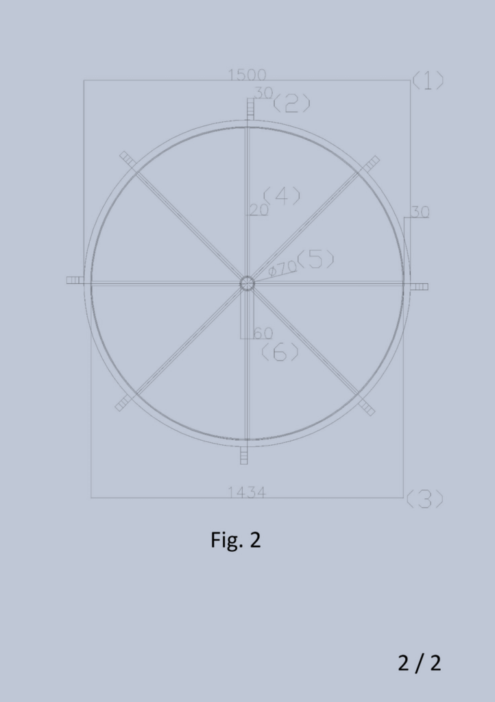
FIG. 2
Legend Fig. 10: (1) polyethylene pipe outside diameter 1500 mm, thickness 30 mm; (2) outer polyethylene pipe rib 80×30 with mounting holes; (3) calendered sheet 100 * 5 mm outer diameter 1434; (4) diameter steel round 20 mm; (5) smooth bore tube diameter 70 mm, lung. 80, thickness 3 mm; (6) smooth bore tube diameter 60 tickness 3 mm, length equal to the tube 1.
As mentioned above the flotation tubes for the importance that will assume should be certified both for the outer material in a low or high density polyethylene, both with calculations regarding internal reinforcements, in order to also locate the maximum draft of the same. Furthermore, after the mounting of the reinforcements inside the pipes will be filled with expanded polystyrene, and after the evaporation of the expansion gas definitively capped with circular plates welded polyethylene. The expanded polystyrene not increase the mechanical strength of the pipes but will prevent the entry of water in case of breakage for a long time to allow the repair of the damage without danger of sinking.
The Sintered Expanded Polystyrene (EPS) is derived from polystyrene (chemically called PS) is a major plastics which are derived from petroleum. The EPS is a lightweight, rigid foam material, derived from petroleum composed exclusively of carbon and hydrogen atoms. It ‘a closed cell structure capable of retaining the air inside them. At the compact polystyrene is a rigid material, colorless, transparent which finds application especially in the packaging and in those fields which require an easily workable polymer, transparency, good thermo-mechanical performance. The EPS is one of the most important forms in which the polystyrene is employed. To obtain it melts a blowing agent in the polystyrene (commonly pentane) and it is treated with other additives to confer resistance to fire. The product is presented in the form of glassy appearance granules (beads), of varying particle size (0.3 to 2.8 mm) according to the purpose which it is intended.
The expansion, namely the chemical-physical process that leads to the formation of “beads” of polystyrene, is by administration of the energy expandable polystyrene – the raw material – without the use of CFC. Putting in contact the beads thus obtained with water vapor at temperatures exceeding 90 ° C, pentane contained in them expands causing an increase of their initial volume up to 20-25 times and by forming inside them a closed cell structure that It holds within itself the air and gives the product its excellent thermal insulation properties. To obtain the EPS is still need a further operation called “sintering” which is the welding process and the compaction of the expanded polystyrene beads; this implemented happens by subjecting the granules again to the action of water vapor that joins them together, to form countless articles: blocks of several meters, the molded using a thermoplastic process of “injection”, etc. To give the precise technical features products are added various additives. It is used for water repellent of stearates. The sintered expanded polystyrene has a density generally comprised between 10 and 40 Kg / mc, and is then constituted by the average of 98% air and only 2% of pure structural hydrocarbon material. Pentane used for expansion, it evaporates at the end of the process in which, against every stereotype, are not used chlorofluorocarbons that are harmful for the ozone layer.
Technical features:
The density of the expanded polystyrene is between 0,02 e 0,06 g/cm3.
The thermoplastic polystyrene is physiologically harmless and also allowed for packaging of food products. The same also applies to the heat-insulating material. In the production of EPS they are not used, nor have ever been used, chlorofluorocarbons – CFCs – harmful to the ozone layer surrounding our atmosphere. The EPS has no nutritional values able to sustain growth of fungi, bacteria or other microorganisms so it does not rot or mildew. The EPS does not constitute food for any living being. The foam does not burn a high flame, but softens at from 95 ° C to 230 ° C gives off decomposition products are flammable; between 450 ° C and 500 ° C ignites spontaneously. In the combustion of polystyrene are formed of acrid odor gases (CO, styrene, benzene, toluene, anti-flame agents) which, however, are not toxic, excluding CO.
Luigi Antonio Pezone