Phosphor removal from detergents wastewater and greywater recycling system for flushing
Toilets.
European patent application EP 1 860 072 A2 published 28.11. 2007
The undersigned holder of patent filing no. CE2006A000014 of 22/05/2006 named “water recovery system for toilet cleaning” of which he claimed the priority, in this European patent, which no European and world country has achieved, demonstrating that world governments do not know and do not want to apply the scientific organization of work to the environment, has completely innovated the first intuition by adding to the physical treatments of the water provided, a chemical conditioning with lime that breaks down the phosphorus that is creating many damages to the environment and many innovations that make the procedure aimed at this goal possible. Recycling has also been extended to public premises such as motorway, railway, cinema, etc. service stations, where the sink water used by millions of people a day is discharged into the sewer or sent to expensive purification treatments; instead, it could still be reused locally to feed the toilet flushes, present in the same room. the accumulation in maxi built-in boxes, the system camouflage of all the components make the system invisible, as well as useful. At present, there are no water recycling and treatment plants conceived so economically, miniaturized and camouflaged.
Description
The writer and patent holder n. CE2006A000014 of May 22, 2006 having as title “water reclaim plant for the WC cleaning” for the reclaim of home sanitary water with max. flows of 15 1/min., claims the partial priority of the project, has studied further innovations applicable every day by common people. They could in this way reclaim water and improve the environmental situation. The printouts illustrated in the lay-out drawings (FIG.1) and the electro-hydraulic scheme (FIG. 2) refer to a public place in which the reclaim of water used for the personal hygiene is applied as well as its reutilization for the WC and urinals cleaning; it offers many technical innovations improved after a first intuition and can be applied both on house plants and in many other branches. On a house plant the percentage of consume water reclaimable for the WC use represents the 25% of our per capita consumption. It is totally obtainable from the water used for the personal hygiene, about 35%, and it is less polluted than water coming from the kitchen. In public places the reclaim percentage reaches the 100% and the whole consumption is halved.Important novelties are:
the chemical precipitation of the phosphorous present in the detergents and inserted in the recirculation phase can be broadened to the wastewater not directly involved in this process. As the phosphorous is one of the main components of the synthetic detergents and it is spreading in exponential way helping the eutrophication of lakes and natural waters, it has been inserted in this project. The city wastewater can contain phosphorous till a max. of 20 mg/l of which the 75% is of inorganic nature; the secondary treatment (Imhoff) removes a max. of 2 mg/l and the whole remaining part is discharged into the final effluent. Considering that not all the effluents are depurated and not all the purification plants are efficient, the reasons of the phosphorous diffusion appear clear. The difficulties of the biological treatment plants active by means of micro-_organisms are due to the slow process and it becomes slower by increasing the quantity to be treated. The process of a chemical removal is expensive and complex. The treatment with lime, moderately – priced, increases the pH of the sewage for the necessary contact time and it is not compatible with the other pollutants contained in the sewage. Other innovative procedures are in progress of experimentation but the undersigned thinks that neutralizing the detergents soon after their use and before mixing them with other polluting substances, simplifies the operation and, at the same time, cuts the prices by using lime. Small lime quantities, dosed in the collector used for the recirculation (fig. 4), reach the reaction point with the phosphates and let them precipitate in a mineral (hydrossil – apophyllite) extractible (with the calcium carbonate and with other secondary mud produced by adding lime) from the hydraulic ejector conceived in this project.
The mud with pH 11 is discharged into the faecal column helping to speed up the depurative process of the excrements. It disinfects the cesspool wastewater and corrects the mud acidification. With this system the addition of lime in the cesspool will not be necessary after the expurgation.
The self – cleaning water filter removes the mud produced rendering ordinary cleaning unnecessary; other
the undersigned thinks that neutralizing the detergents soon after their use and before mixing them with other polluting substances, simplifies the operation and, at the same time, cuts the prices by using lime. Small lime quantities, dosed in the collector used for the recirculation (fig. 4), reach the reaction point with the phosphates and let them precipitate in a mineral (hydrossil – apophyllite) extractible (with the calcium carbonate and with other secondary mud produced by adding lime) from the hydraulic ejector conceived in this project.
The mud with pH 11 is discharged into the faecal column helping to speed up the depurative process of the excrements. It disinfects the cesspool wastewater and corrects the mud acidification. With this system the addition of lime in the cesspool will not be necessary after the expurgation.
The self – cleaning water filter removes the mud produced rendering ordinary cleaning unnecessary; other
important novelties are:
the water accumulation in the floor, necessary for a recirculation or for a contact with the coagulant, can be increased, extending the collector or creating parallel lines. It is not stagnant and does not smell as it is placed in a strongly basic environment;
the small preparer of the coagulant solution with all the control devices at a low tension and the necessary accident – prevention devices allow its installation in a private environment; space is not necessary because the plant is compact and camouflaged in the walls and floor.
Nowadays similar plants do not exist. They are simple and targeted to a partial water reclaim or to the specific detergent treatment before its discharge.
Referring to the figures mentioned before, the functioning is the following: the waste water from the sinks are piped into an underground collector (a) and into more sumps (e) of standard dimensions, containing the necessary recycling equipment. These are then lifted to the maxi boxes where they are accumulated and then reused before being definitively unloaded into a sewer through WCs and urinals.
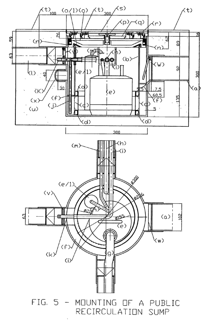
In the sump on fig. 5 a foam protection cylinder (b) holds the floating substances and makes the water pass through a filtering net (c). It is recalled by a lifting motor-driven pump (e). The heavy particles piped by the chute (f) sediment in the air space between the internal walls of the filter and the external wall of the cylinder, out of which they are regularly sucked up by an hydraulic ejector (k) fed by the water system or by compress air before being sent to the sewers.
The flushing system (with water) with a separate pipe (h) feeds 2 tubular rings with rectangular section. They are incorporated in the structure of the foam protection cylinder (b) and are provided with holes placed toward the filtering net (d) for the regular and timed filter cleaning.
The filter and sump cleaning will be effected in different moments. The cleaning of the filter can be planned, requires a few seconds (20 – 30 sec) and is effected with crossed sprinklings of water, located on the top and on the bottom, with an angle of 30° towards the filtering surface.
The cleaning water brings in the sump a further important, secondary effect: in a few seconds 4-5 changes of water (in volume) will be let from the sump into the sewer through an overflow, removing all the sedimentary and floating substances and cleaning the sump and foam protection cylinder walls. The non-return door (v) located on the drainage toward the sewer (1) avoids the passage of bad smell while the door – frame in the discharge hole establishes the threshold of its skimming sustaining the ejector (k) with a calibrate hole; the door position (not on the sump wall but in the discharge hole) allows the taking apart of the ejector and of the cylinder; the door can be disassembled as well.
The cleaning of the sump with the hydraulic ejector (programmable) has an advantageous secondary effect. Through the introduction of a fluid under pressure into the waste pipe, eventual clogging are prevented. Both cleaning actions should take place at night not to interfere with its normal functioning.
The triple cleaning action (filter, sump and discharge pipe) renders the system totally free from manual cleaning. The sump will be then opened only in case of extraordinary maintenance caused by a damage of the lifting motor-_driven pump (e). This will be detectable trough a warning light located on the control board.
A further device for the manual cleaning of the collector is located at its ends. It is provided with a direct connection to the water distribution collector through an interception valve (or solenoid valve in case of automatic cleaning) connected to the detail 4 through reduction PVC joints (d).
Each plant should be provided with at least 2 lifting sumps in order to prevent sudden streams of water, as it usually happens, and to have a reserve in case of pump damages. The sumps can be matched in series or in a parallel way thanks to the arrangements provided in the project of the sumps and matching accessories (FIG._4). Each sump allows a recirculation of about 100 litres per minute. In the fig._1 a third sump (e/_1) is provided for. It allows a sewage recirculation that renders the coagulant diffusion in the dosing plant (1) uniform. This sump is similar to the others except for the pump use.
The single maxi box (FIG. 2-3-13-15) will be fed from the bottom and on both sides. In this way an upward flow is granted in the whole tank avoiding eventual sedimentations. For the same purpose the bottom has a hopper form that renders the flow towards the discharge and its cleaning easier thanks to the speed of water in the parts concerned by opening the outlet hole.
The new “maxi boxes” allow an accumulation of about 57 litres of water and 6-8 consecutive draining, corresponding to the common boxes, without using the water system. Once the supply of the reclaim water is over, the feeding will be led by the water system. This will be automatic, without the support of complex devices, through a ball cock overflow valve. The diaphragm, closing device is located at the bottom of the tank and therefore it is constantly kept closed by the level of the reclaim water.
As already known, the discharge hole of the maxi box is like a discharge mouth under head and its delivery depends upon the tank level that can vary from about 20 cm till a max. of 130 cm.
As the maxi box is under atmospheric pressure, the outlet delivery of the tank depends only upon the geodetic height. The outlet section of the box will therefore have a theoretical speed of 1,98m/sec and 5,05 m/sec, according to the known formula of the Bernoulli’s theorem (V = n 2xgxh); (without considering a further difference in level till the outlet and the localized discharge losses that would balance the difference of the final delivery, as these are proportional to the speed square) in order to balance the initial conditions between the min. and max. levels and to deliver approx. the same water quantities for each operation, the opening discharge time at a min. level should be 2.55 times higher than the max. level (5,05 / 1.98 = 2.55). The intermediate levels will be contained in this max. ratio according to a curve that will be experimentally determined.
The adjustment of the opening time to the water level of the maxi boxes, so far the outlet vent concerns, will be possible with the following facilities: a special electrical – electronic circuit, a continuous level controller, a mini electrical actuator mounted outside on the top of the maxi box, and a closing device of the discharge hole, activated by the actuator (fig. 14).
Without dwelling on the electrical system that will be realized according to the plant needs, we can assert that the plant (big or small) will run as if it only had one storage tank (by the principle of the communicating vessels). So far the lifting sumps concern, the level gauges of gear and arrest of the motor-_driven pump will be positioned at slightly different heights so that the first motor-_driven pump starts, followed by a second one. If the level increases, a third one will start and so on, depending upon the plant size. Only one level transmitter in any of the maxi boxes will be enough.
to determine the different discharge permanence time in the inlet (due to the electrical actuators started one by one by low tension buttons or by photocells).
The whole automatism is based on the thousand volt Ampere (4-20 m a), proportional to the buoyancy and transmitted by a piezoresistant probe fed in c.c. at 24 V c.c., placed into the main maxi box.The signal coming from the whole measurements (0 – 130 cm) will be transmitted by a level meter to an electronic module supplied at 24v c.c.; this will allow to get n._6 functioning thresholds corresponding to 12 outlets among which n. 6 will be used by the timer linked up to the control relays by the actuators of the WC maxi boxes and n._6 by the urinals that requires longer times.
The precision of the system is ensured by the following parameters: 0.2% of the value transmitted by the level gauge and 0.05% of the electronic module.
Here follows the description of the drawings in general and of those related to the single components:_
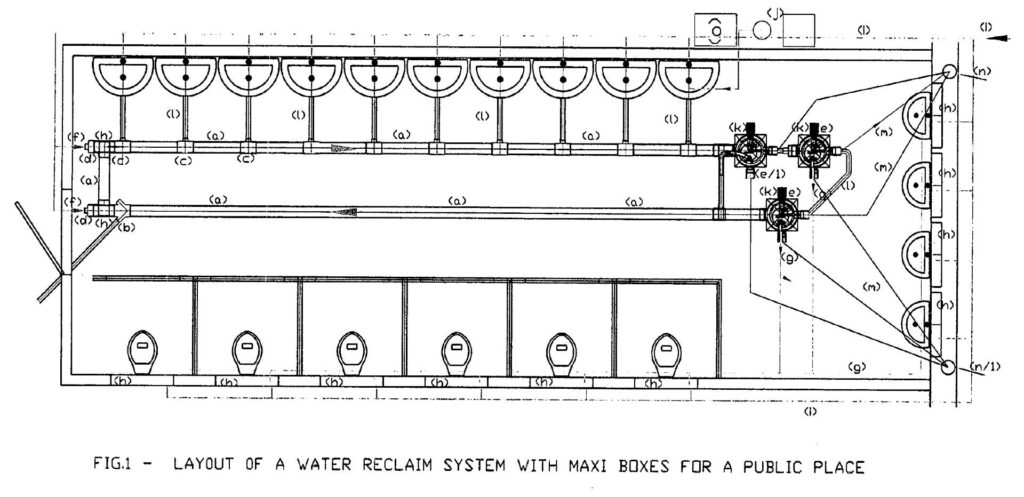
FIG. 1 – typical lay out of a reclaim water plant in a public place, where the main components and the possibility of matching them together can be noticed:_
(a) tubular element of the collector (fig. 4/a); (b) discharge connection at 45° (fig._4/b); (c) connection at 90° (fig._4/c); (d) end elements (fig. 4/d); (e) and (e/_1), lifting and recirculation sumps (fig._5); (f) water connection to the water system for the cleaning of the main collector at the ends. A conical spraying nozzle is screwed as in 4/d; (g) water recirculation delivery; (h) rinsing maxi box (h); (i) water distribution from waterworks; (j) chemical dosing system (fig. 8); (k) extractable plate (fig. 9 -10), (m) PVC tube j 40; (m) discharge tube in the sewer j 63; (n) discharge collecting column for grey water; (n/_1) discharge collecting column for waste water coming from w.c.; (o) hot water boiler.
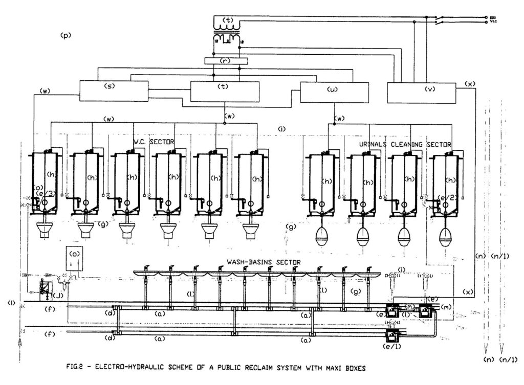
FIG. 2 – electro-_hydraulic scheme relative to the plant on fig._1. The connections between the various sections can be noticed as described in the premises and not visible in the lay-out. The references are the same of figure n._1 but they are now integrated with those not shown in the lay-_out: (o) level transmitter as pieozoresistant probe, feeding 24 V. c.c., outlet signal 4-20 mA; (p) electric control board; (q) tension transformer 220/24V c.a; (r) current rectifier 24 Vc.c. (s) circuit for the level regulation; (u) circuit for the draining regulation in the line “urinals”; (v) feeding circuit for the lifting motor-_driven pumps; (w) electrical connections lines under low tension; (x) electrical connection lines 220V c.a.;
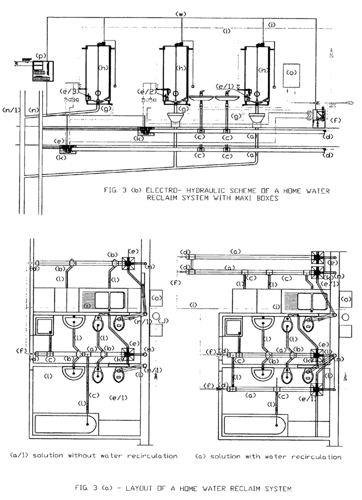
FIG.3 – it shows the layout of the first deposited patent as well as the electro – hydraulic scheme of a home plant integrated with the innovations proposed in this project. The description is not reported because the components and references are the same of fig. 1 and 2. In this case a second recirculation sump has been added as well as a sewage equalization for a treatment with coagulant; the reclaim is performed by matching the collectors sumps, as reported in the figure. The recirculation pump sends the sewage into the collector through a hole located in the frame of the non – return door (w). creating a one-way flow towards the lifting pump positioned in the other branch of the manifold. A further possibility is to place the recirculation sump on the opposite side to the lifting sump if there is the possibility of discharging the sludge and supernatant from that side.
A further novelty is due to the presence of a second system in the adjacent room, which represents the kitchen, although not interested in recycling (to clean the toilet, statistically it is sufficient to recover the personal hygiene water, which is less polluted than those of the kitchen). This second system has been designed exclusively for the neutralization of detergents and other pollutants compatible with the procedure envisaged. The operation of the two systems is the same, with the only difference being that the kitchen lifting pump. instead of lifting the water to the maxi cassettes, it sends it to the gray water drain column with a timed interval (which ensures the necessary contact time for the coagulant) and with the consent of the level switch. The recirculation sump pump, on the other hand, performs the same task described above to facilitate the mixing of the coagulant through the connections (l). The water and supernatant that exceed the maximum level when the pump in charge of the discharge does not have the consent of the timer are drained by the overflow. The sludge extracted from the ejectors is introduced into the fecal column, conveyed with the feces will help to accelerate the decomposition process.
The same scheme can obviously be applied to the kitchens of public systems, replacing the well of fig. 6 with that of fig. 5, larger in size. 7 Returning to the domestic system, the 1% diluted lime solution provided for chemical conditioning, coming from the doser, proportional to the total consumption flow rate of the water, will be divided into three branches with equal flow rates, two of which are conveyed to the collector. in the kitchen and one in the recirculation manifold to respect the statistical percentages of consumption. Any distribution errors will be compensated in the Imhoff tank of the building where the purification cycle continues as described below, fig. 8. For public places it is advisable to use independent dosing systems for each room.
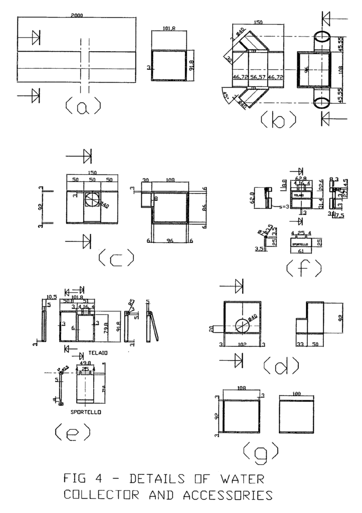
FIG. 4 – water collector details and connection accessories. You can notice:_
(a) the standard pipe can be cut and coupled to the other components in order to have an accumulation and collecting
system before the lifting sump. The standard section will be used for the home plant as well to cut the component
prices and establish a common principle of plant modularity between the two plants.
(b) discharge connection element 45°, equipped with two couplings j 40 (arranged in a non – return door to be used
for the collector cleaning under pressure);
(c) discharge connection element 90°, equipped with two couplings j 40 (arranged in a non-_return door to be used
for the collector cleaning under pressure). It allows a discharge inlet in the collector and the parallel connection of
the same collectors;
(d) this element allows the collector closing, by putting on the coupling j) 40 a commercial cap, and a serial connection
of the two lifting sumps by using the corresponding coupling on the sump;
(e) the non-_return door has the same dimensions of the collector section. It is possible to build it in the internal
housing of the sumps (fig. 5) and in the internal housing of the sump (fig._6) on home plants. The door occupies only
one half of the frame. The other half is closed to allow the passage of the recirculation pipe in the sumps assigned
to this function.
(f) the non – return door has the same dimensions of the connecting holes on the recirculation sump (home plants
40 x 40 mm or public plants 63 x 63) and has four important functions when mounted on the overflow discharge:_determining the discharge outlet position, using one of the three sump arrangements; establishing the max level of the overflow discharge. It is determined by the fixed part of the containing frame; avoiding the passage of bad smells coming from the sewage; calibrate support for the passage of the sand extraction ejector; Both the doors (e) and (f) are built into the housing and are stabilized by a rest located in the housing and blocked by a spacer applied on the foam shield cylinder:
FIG. 5 – already mentioned before. It reports the whole mounting of the “lifting sumps” in longitudinal and horizontal sections. Following the water flows, the following elements appear clear: (a) the collector and a non-_return door (W) mounted on its ends. Its gravity function avoids a water return in the collector during the flushing phases, as above described; (b) the foam shield cylinder allows the sump to divide the floating substances, just like the Imhoff tanks. Its circumference enters partially the closing sump cap and compresses the gasket avoiding the coming of water within the cylinder; (c) a 200 micron filtering net in polyethylene; (d) flushing rings, particulars b and e, rectangular section, on the top and on the bottom of the net, each one having 32 holes oriented with a 30° inclination toward the same net. (e) motor driven pump for clean water with the following technical data: delivery 1/min. 100, discharge head 3.7 m, nominal power KW. 0.5, feeding 220 V mono phase, adsorbed current 1.43 A; (e/_1) floating switch for the motor – driven regulation; (f) conveyor point for the sediments in the extraction point. It also avoids that water coming from the bottom could open and not close the non -return door; (g) flexible pipe for the delivery of the pump with rubber holder.”; (h) flexible pipe for flushing water, filtering net j16 x 2 mm; (i) flexible pipe for the feeding the ejector used for the sand extraction j 14 x 2 mm; (j) flexible pipe for sand extraction j 8 x 1 mm; (k) ejector for sand extraction fig. 6; (19) connection to the sewage discharge; (m) submergible cable for the pump feeding; (n) neoprene gasket c shaped 16 x 12 x 4; (o) gasket compression cap; (o/l) gasket foam shield cylinder; (p) expansion screw for the cap closing; (q) traction disk j 138 mm; (r) sump cap and anchor base for tile holder support fig. 10 (the other important functions later described); (s) pile holder support fig. 11; (t) floor pile; (u) serial connection coupling of lifting sumps; (v) smell protection door; (w) non – return door to the collector (a) with frame; (x) closing cap.
Having described the sump functioning we can state that it is “self – cleaner”. It does not need manual cleaning. This condition allows him to be camouflaged into a room and to be placed under floor piles, as in fig. 5.
The accessibility is granted by the extraction of the pile (t) and by its relative support (s) by means of the spread commercial suckers. This solution allows a camouflage with a pile 30×30 cm, or with a pile composition of smaller dimensions. They could be cut and glued on the support (s) or reach a higher format of 33×33 cm with a light lateral sharp rise.
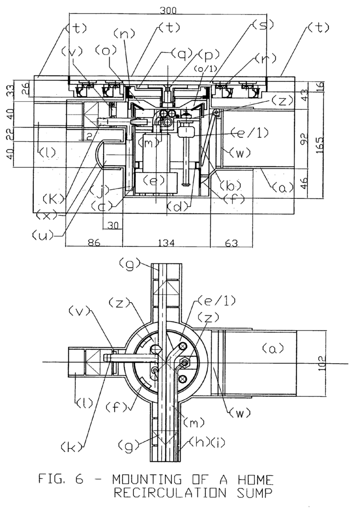
The FIG. 6 proposes a lifting sump on a home plant updated with the newest renovations. As for the layout the description is not reported because the component and references correspond to the fig. 5. Only the following details are added:
Per il lavaggio della rete filtrante e l’alimentazione dell’eiettore di estrazione sabbia è stato usato un solo tubo di alimentazione per motivi economici, conseguentemente le operazioni saranno fatte contemporaneamente con una sola elettrovalvola ( ma nulla vieta che possano utilizzarsi elettrovalvole separate o valvole di comando manuali) ; è stata prevista una staffa (z) per il fissaggio della mini elettropompa del livellostato, i quali essendo molto leggeri, senza fissaggio sarebbero soggetti a movimenti indesiderati nella fase di lavaggio con acqua di rete;
For the washing of the filtering net and the feeding of the sand extraction ejector, only one feeding tube was used for economic reasons, consequently the operations will be done simultaneously with a single solenoid valve (but nothing prevents that separate solenoid valves or manual control); a bracket (z) has been provided for fixing the mini electric pump of the level switch, which being very light, without fixing they would be subject to unwanted movements in the washing phase with mains water;
n. 3 electric pumps with 12 V DC power supply with slightly different characteristics, interchangeable in the cockpit, the individual performances are shown below:
current intensity (A h) 09- 1.7 A 2.0 – 2.5 A 2.1 – 2.9
max flow rate (l / min) 10 12 18
maximum head (m) 6 6 10;
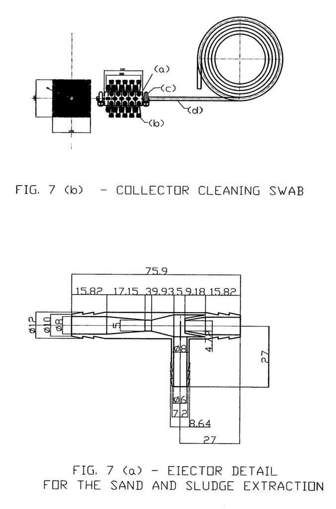
The FIG. 7 (a) shows the detail of the extraction ejector that will be used for the sand and sludge extraction from the sump (and for the water and air mixing in case compressed air would be used for the collector flushing): it is based on the Bernoulli principle that establishes how the sum of the energy forms of a fluid in movement in a closed circuit is constant. Increasing the speed the pressure decreases and vice versa. With a great section reduction the speed will be higher and the pressure will strongly decrease till when a void will be created. Its grade is proportional to the quantity of energy transformed in the section variation; this void allows a lifting of fluids and particles matched to the place where the phenomena is generated. The system is commonly called Venturi effect.
The Fig. 7 (b) shows the detail of the cleaning swab, used for special maintenance. It can be inserted in the collector after the removal of the lifting or recirculation sump’s door. It is made up of: (a) PVC support, (b) synthetic bristles, (c) clamps for metal cable, (d) cable in galvanized cable._
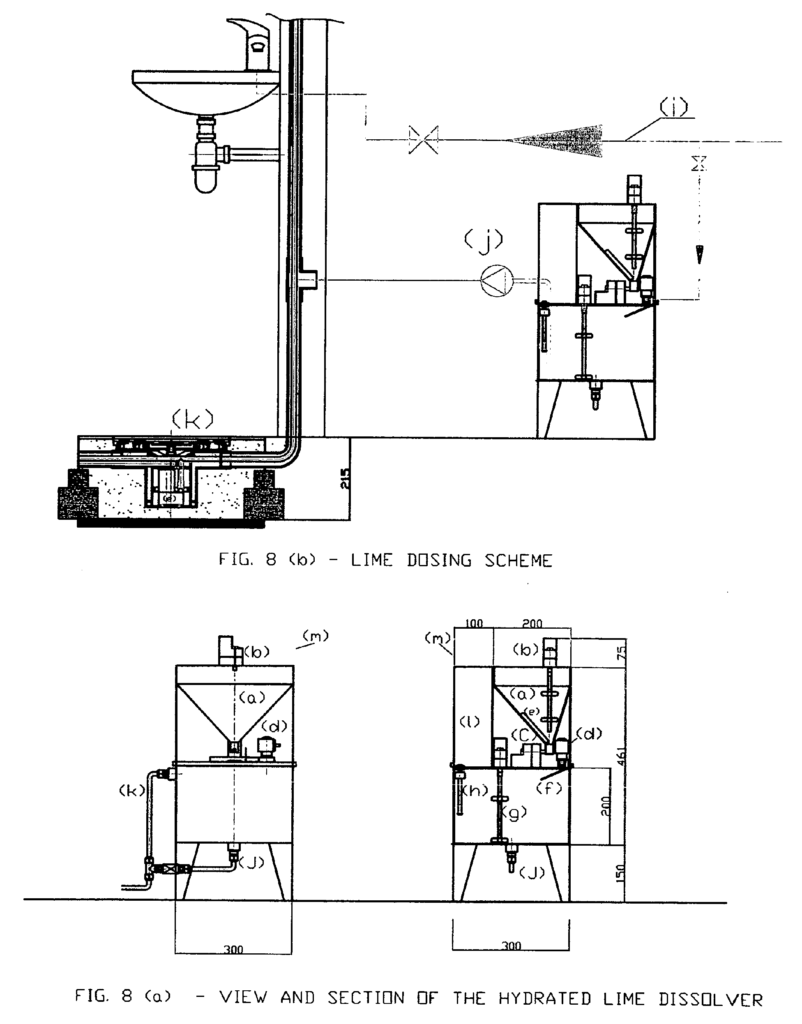
The FIG. 8 shows the plant for lime dosing and dissolution.
It is a small plant for the chemical conditioning of sewage and it focuses on the phosphorous precipitation bringing beneficial effects to the same ecirculation.
The conditioning takes place by adding a coagulant to the sewage. It is lime hydroxide, also called lime (hydroxide), alum or aluminium sulphate hydrate, chloride or ferric sulphate hydrate. The main component is lime and it must be always present. We refer to lime in the dimensioning calculation while other components my be chosen in special cases according to the water analysis. The hydrated lime reacts with the alkalinity of refluent water independently from the phosphates quantity and produces calcium carbonate, the main responsible of the S.S. removal (suspended solids): Ca (HCO3)_2 + Ca_(OH)_2 ® 2CaCO3 ¯ + 2H2O._
When the pH of the refluent water becomes higher that 10 – 11 by adding lime, the overplus calcium ions react with the phosphates and precipitate in hydroxidyapatite (it is a mineral present in bones and in some rocks and is made of 60% calcium, 30% phosphorous, 10% oxygen and hydrogen): 10Ca2+ + 6Po4
-3+ 20H- « Ca10 (PO4) * 6_(OH)2¯Sludge and sediments produced with both reactions above described as well as other secondary minerals will be collected in the recirculation sump. They will be then extracted from the hydraulic ejector and piped into the faecal columns, toward the Imhoff tank, before being thickened. The process will not cause bad smell as it occurs in a basic place.
The quantity of lime required can be approx. 1.5 the alkalinity in mg/l of CaCO3. Considering a medium alkalinity value corresponding to a medium value of 150 mg/l of CaCO3, the calcium requirement will be of 225 mg for a single litre of treated water. This value will be rounded off 250 mg/l, considering the impurities and particles still present in the lime.
As the delivery is very small, a lime solution of 1% has been used. This will not cause aspiration problems to the pump.
After a closer experimentation we could increase the lime milk concentration. For two plants, for ex., we could have the
a) A home plant recovers 250 litres a day (for a 4 members family) and consumes about 1.0 m3, comprising the non – reclaimed water conditioning discharged from the kitchen. It needs 250 gr of lime a day and 25 litres of dosing water, partially recoverable from the recirculation. If we use the coagulant solution directly in maxi box, we need only 75 gr. of lime a day.
b) A public plant that recovers 5 m3 a day needs 1.25 Kg like a day and 125 litres of dosing water, totally recoverable through the recirculation. The dissolver shown in fig. 8 (a) allows a 10 kg load of hydrated lime and, in case it would be used for the two plants above mentioned, it could have an autonomy of about 40 o 160 days (on a home plant) and of 8 days (on a public plant).
We assume that a maintenance staff is available. It will be composed by the following parts: (a) stocking hopper; (b) lime powder agitator (in order to avoid a thickening). N._6 rev./min., gear 0.5 A; (c) dosing screw n._12 rev/min., gear 0.5 A; (d) feeding water electrovalve .”; (e) electrical resistance for the absorption of the granulate humidity, 10 w with thermostat; (f) hydration chute fed by the electrovalve water d, on which powder fells once out of the hopper; (g) agitator for lime milk n. 500g/min., gear 2A; (h) level gauge for the solution reinstatement (it allows the opening of the electro valve and the movement of the powder feeding screw); (i) overflow discharge, (j) bottom discharge; (k) electric control board;
(m) protection covering (it contains all the control board and the parts in movement) thought for the children safety in the home applications.
The dosing scheme on fig. 8 (b) uses the same identification letters for a volumetric counter with 24 v c.c., having an outlet signal in milliampere, and is associated to a dosing pump that takes the product from the collector and pipes it into the recirculation sump. In order to have a well diluted solution, ready for the use and constant in the composition percentage, the level gauge will be programmed to start when 7.5 litres have been consumed within 30 min functioning on a home plant and 3 min on a public plant. The re-establishment of the 7.5 litres should happen within 1 minute in order to face any problem. The screw will have a hydrated lime delivery of 75 gr/min. (250 mg/_1 * 3 min. * 100 It/min. /1000).
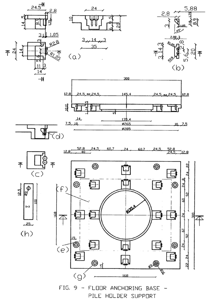
The FIG. 9 shows the details of the anchoring base of the piles holder supports (fig. 10). It covers the recirculation sumps on public and home plants (fig. 5 and 6) together with the accessories m, o, p, q that differs for the two tasks, as shown on fig. 5 and 6. The detail is in plastic material and allows with the pile holder support on fig 10, a sump camouflage with piles of 20 x 20 cm. 20 x 25cm and 30 x 30cm. It is easily adaptable to the 31,5 x 31,5 and 33 x 33 cm formats as well. The anchorage occurs through the stainless steel clamps of the support that are coupled in the sumps of the basis. The drawing shows the following details: (a) the sump detail; (b) the detail of the anchoring nib to be mounted on the sump as it can not be realized in a single piece; (c) and (d) the mounting detail of the nib (b) in the sump (a) and its fixing with two self threading screws length j 2.9, 6.5 ISO 7050 stainless steel; (e) the pile shape 20 x 25 cm; (f) the pile shape 20 x 20 cm; (g) the holes for the mounting of the anchoring clamps in the cement block; (h) detail of the anchoring clamp.
Looking at fig. 5 and 6 we can notice that the access to the sump can occur through a pile (t) and its support (s) removal by means of a common commercial sucker and loosing the screw (p) that presses the gasket (n). After these operations, as in the case of fig. 5, the basis that serves as a cap can be raised. As in fig. 6 only the central part has to be raised (details n,_o,_p,_q) while the basis is depth in the cement block and in the sand of the whole walls by means of the anchoring clamps (h)._
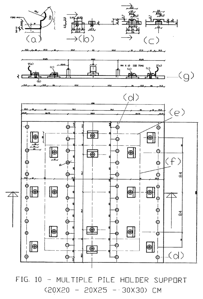
The FIG. 10 shows the multiple piles support for those piles having as dimensions 20x20cm, 20x25cm and 30x30cm, as well as the format 33×33 cm without fittings, both on the wall and on the floor. It is equipped with anchoring clamps. A multiple function has been provided in order to avoid single moulds for single pile formats. The formats of inferior nominal dimensions will be cut along the apposite lines, as shown in the figure, while the bigger formats will be fixed with a lateral sharp rise.The clamps number per format is 8 but not all the applications require the same extraction force. Those on the floor require a higher force in order to avoid its movement due to people’s weight; those on the walls require an inferior force and an inferior number of clamps. This is the reason why the clamps are interchangeable, fixed with screws, dismantled and of various sizes (from 6/10 till 10/10 mm). Special care has been turned to the floor application that allows to embed the clamp support fixing in the anchoring sump for a higher stability. This support is like a spacer when tanks and flushing boxes are covered. In this ways an air chamber is formed between the tank and the covering avoiding a condense formation of the walls. The drawing shows the following details: (a) anchoring clam derived form a stainless steel ribbon width 12 mm, thickness 0.6mm – 0.8 mm – 1mm; (b) thread plaque M4 in light alloy; (c) plaque and clamp housing; (d) flared holes j 7 for a supports coupling, see fig. 12; (e) cut shape 20x25cm format; (f) cut shape 20×20 cm format; (g) mounting section of the spline with a plaque in the support, screwed with stainless steel M4 x 10 ISO 7046.
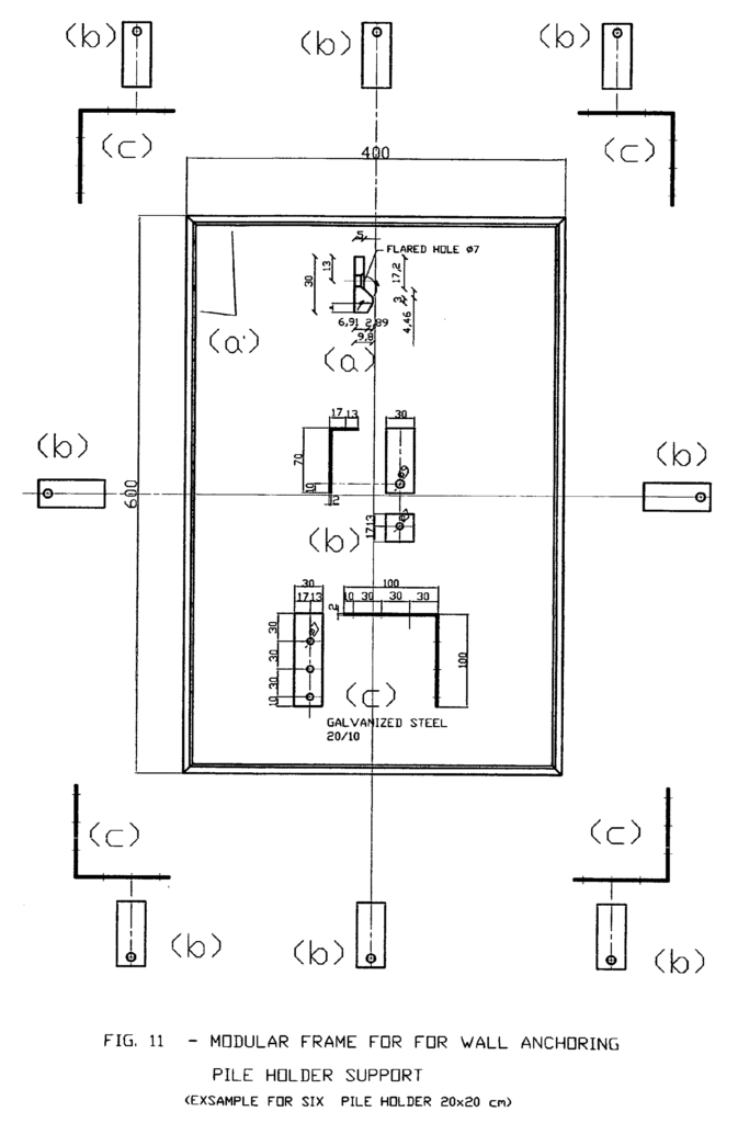
The FIG. 11 shows the frame for the wall anchoring of the support caps (fig. 10); this frame differs from the previous anchoring system because the whole border has a shaped section similar to the linking nib and has no fixed anchoring positions. The shaped section can be mounted in the sumps and can be used both with single piles and with multiple compositions, see fig. 12. With the other anchoring sumps it allows a more complete linking of the pile supporter to the wall. The drawing shows the following details: (a) the border section is in plastic and has a mounting hole; (b) the anchoring clamps for the galvanized – steel wall; (c) union element in galvanized – steel for the frame composition.
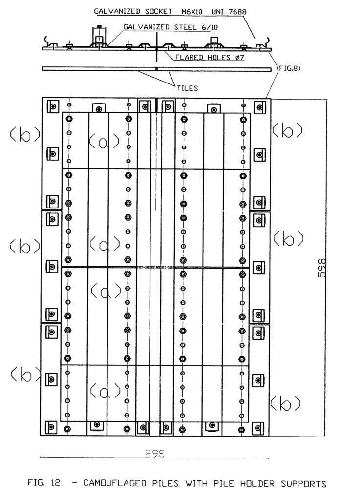
The FIG. 12 shows an example of multiple support composition for removable piles (b) associable to the compatible frame (fig._11); this solution is interesting for covering the hydraulic connections as well as the interception valves, electric equipments, distribution collectors of the hydraulic and heat plants, substituting those in plastic or plate commonly used. The pile holder supports are coupled with a panel of pre-_printed shaped plate, as if they were an only one big pile. The internal clamps are not mounted and the connection will be effected with the peripheral clamps in the modular frame. The composition escribed in the drawing is made of n._6 pile holder supports and n._4 coupling plates. Further combinations are anyway possible for each pile format.
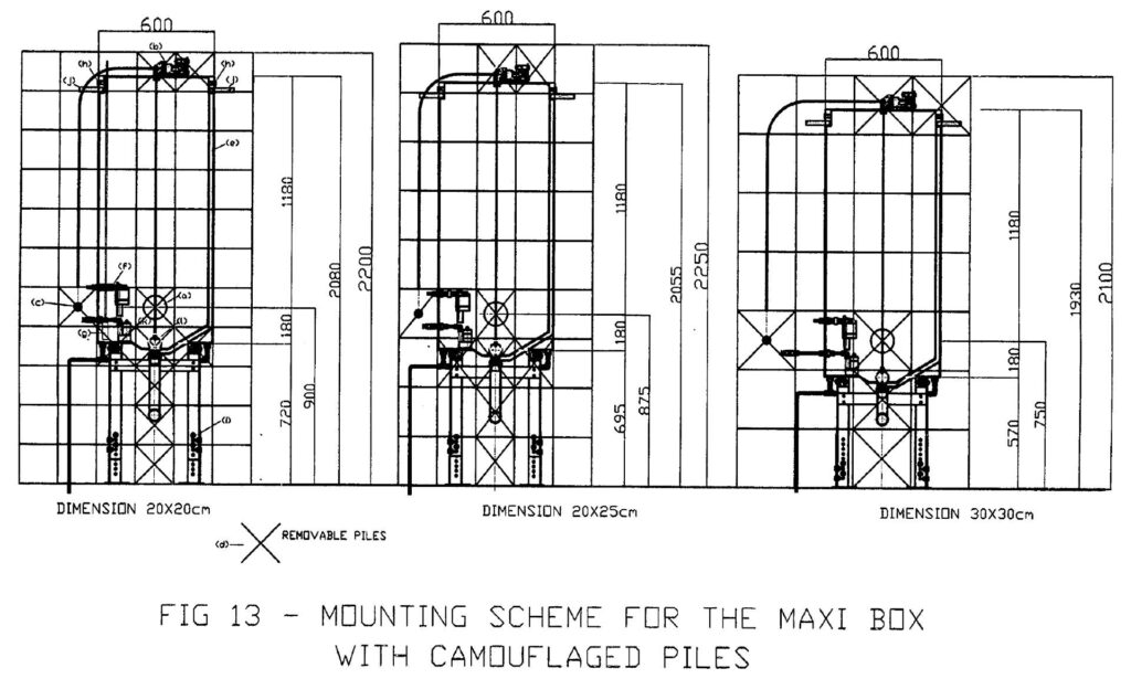
The FIG. 13 shows and example of a maxi box installation with three different pile coverings on the walls. The mounting height of the maxi box differs on any covering. This is due to the plant camouflage conceived with the same maxi box and tries to render it totally invisible. The camouflage is due to the assembly of the special “removable” piles (d) (fig. 10) in those positions where an inspection access or a facilities maintenance is necessary. The automation does not require maneuvering facilities in full view. The necessary positions for the before mentioned access are: the porthole (a), the top, where the control gear is mounted on (b), the eventual driving button (c). Other positions can be inspected at the users’ discretion. The criteria used to render eventual accesses possible, after the piles’ dimensions, are the following:_
to centre the porthole position (a) with the centre of an extractable pile (d) starting from the floor. This height varies with the format and dimensions of the pile selves. In the examples shown in the drawing we can notice three different heights for the portholes: 900mm, 825mm and 750mm. Superimposing the three figures we can notice that the control gear (b) (whose base is 1.180 mm from the porthole centre) is wholly accessible by removing the marked piles. In order to render the piles extractable (d), the anchoring sumps have been obtained for pressing (fig.) on the surface of the tank’s wall. The pile out of the maxi box surface is anchored to a frame (fig._11) and placed next to it, in the position required. The components for the camouflage allow the use of the three most common piles formats without adjustments and with a simple bricolage they can be adapted to other piles formats.
Other important features are:_
the overflow discharge (e) included in the tank’s structure. It flows below the discharge buffer ensuring atmospheric pressure in the discharge pipe, also when the buffer is closed, and avoids the sucker effect in the lifting phase of the buffer self;
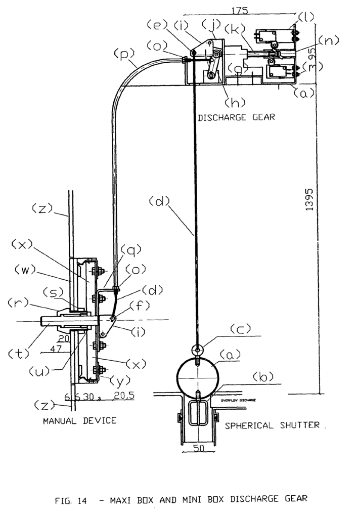
the reserve feeding with the water system as well as the filling valve (f) are in a low position to grant automatically the performances of a common discharge box, without further mechanisms, in case the plant is out of order or recovery water could miss. The level transmitter probe (g) is fed at 24 V c.c. (one for plant); the feeding connection (h) is located on the top on both sides and could be used with the water feeding (without reclaim plant) in those places where the non-_continuous service of the waterworks requires water reserves; the inferior support frame (i) has adjustable legs in order to allow the necessary adjustment for the plant camouflage with the three piles formats, shown in the figure. The superior stabilization of the maxi box in the wall is due to two blind threaded fittings 1/2″ _(J) that allow clamps to be screwed. These are obtained form a pipe of such dimensions. The level transmitter piezo resistant probe is shown in the (k) position while the float shutter in the (1) position. The FIG. 14 shows the whole fixing of the discharge gear. The system is simple and reliable: its hydraulic seal is left to the weight of the spherical shutter and to its neoprene covering.
The selected actuator for the discharge gear functioning is a mini screwed one. Here follow its features:_
feeding 24v/w, nominal power 14w, current 0.6A, stroke 20 mm, speeding 11 mm/sec, protection IP40, strength 27 N, weight 450 gr.
As an alternative, an electromagnetic actuator with the following features can be used:_
feeding 12 v/cc, nominal power 26w, current 2.2A, stroke 20 mm, strength 20N, weight 700 gr.
A manual device could be installed contemporarily to the electromechanic device. It should have a mechanical button that does not interfere with the previous one. They use the same mechanism but they are independent because the shutter closes the discharge with the own weight, independently from the driving gear that opened it._ The urinals will be fed by the maxi boxes as well because they are normally activated by mechanical, timed buttons or by opto – electronic devices with an established interval of 6 – 8 seconds. They can be excellently substituted with the scharge mechanism of the above mentioned maxi box._
The lifting movement of the shutter is obtained by transforming the horizontal stroke of the actuator stem trough the levers shown in the figure:
the stem stroke is adjustable. In the figure a stroke of 17 mm corresponds to a shutter lifting of 14.19 mm and to a horizontal movement of 12.56 mm. It corresponds to the circumference arc that describes the suspending point of the lever (i). The cord of this arc can be considered to be equal to the weight to be lifted (1kg) and is inclined of 48° toward the horizontal plane. As a consequence the vertical component that represents the lifting strain is 1 x cos. 8° = 0.669 kg.
The strength that raises the shutter acts in a horizontal way through a roller frame and the lifting strength is 0.669 x P [(coefficient of rolling friction 0.12 (metal / metal without lubrication (0.3) x the ratio of the pivot ray to the external one of the roller (0.4) J = 0.080 kg._
The initial strain is due to the weight to be lifted x the resistant arm x the friction coefficient / thrust arm = 1 x 14.5 x 0.12 /26.5 = 0.065 kg (it increases by increasing the resistant vertical component). In case of manual devices, the ratio between the push strength and the resistance strength improves considering the lever effect of the auctioning button: the ratio between the arms is 14.4 / 21.52 = 0.672. The lifting strength is 0.080 x 0.672 = 0.053 kg while the initial one is 0.065 kg x 0.672 = 0.043 kg.
The strength ratios described diminish during the closing discharge phase, when the stem telescopes or the manual button is released as the shutter weight must bring the operating levers and the shutter self back to the initial position.
This is very important especially with the manual gear because the shutter fell is avoided even though the stroke is limited to 15 mm: the phenomenon does not exist in case of electrical running as the brake is due to the folding back stem speed (11 mm/sec).
Here follow the mechanisms’ components:_
(a) cast iron spherical shutter, covered with neoprene, for the closing of the discharge hole. Total weight about 1 kg; (b) guide cage and brass shutter centring; (c) brass eyelet for the shutter suspension; (d) stainless steel string j 2; (e) clamp for the suspension string; (f) clamp for the string traction; (g) screw electrical actuator; (h) lever with inferior fulcrum and superior roll; it can be operated from the electrical actuator on one side, and from the string of the manual device from the other side. The lever movement opens the discharge lifting the shutter through the square lever (i); the folding back of the actuator stem or the release of the manual button close the discharge for the effect of the shutter weight trough the same mechanisms; (i) square lever for the shutter suspension; (j) stirrup for the lifting devices; (k) stem with trapezoid screw j 8; (1) stirrup with electrical stroke end for the shutter opening; (m) stirrup with electrical stroke end for the shutter closing; (n) slider for operating, stroke end cams (pipe j 13.5 sp 1.8 mm with inferior and superior groove of 2 mm); (o) stirrup for the electric actuator and control devices; (p) flexible, steel sheathing j5, thread carrier for a manual actioning (it is commonly used on cycles and motorcycles for the cable passage for breaks and change gear); (q) mounting stirrup for a manual actioning; (r) thread button holder bush, mounted on a pile passing hole; (s) thread metal nut for the bush blocking (r); (t) discharge button; (u) thread sleeve for a button directory; (v)_ terminal for the fixing of the thread carrier M5 sheathing; (w) extractable pile with relative support (fig. 10). Its removal allows the access to the actioning device; (x) stirrup support section q; (y) stirrup for the section x fixing; (z) fixed covering piles.
We can notice that the carrier stirrup of the lifting device (J), the electronic actuator (o) and the manual device (q) are independent. The system allows to add a manual and electrical connection in a successive phase, outside the maxi box.
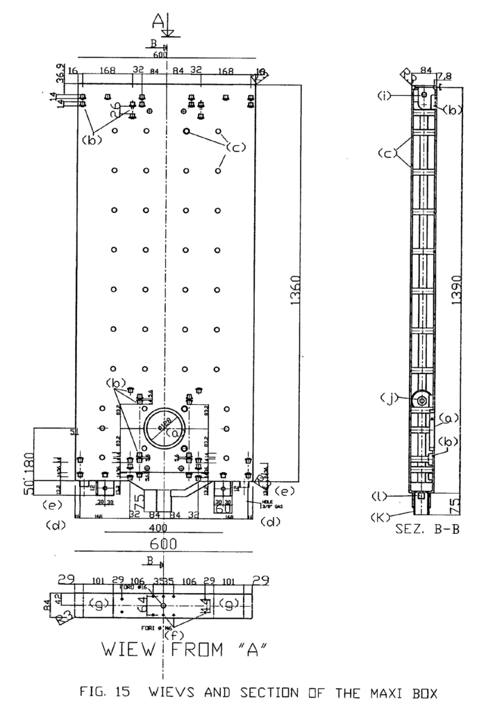
The FIG. 15 shows the building details of the maxi box, whose functional features have already been described with the fig. 12. We can notice:
(a) porthole access for the shutter and restoration valve mounting; (b) anchoring sumps fig. 8; (c) wall connection supports; (d) overflow discharge; (e) feeding connections for the reclaimed water j3/8″; (f) mounting holes of the gear device. We can notice how their symmetry allows a double orientation of the device; (g) removable caps to access to the superior filling valve. Both caps are blocked with the anchoring clamps fig. 10 (a) and the superior profile of the accessible spaces is identical to fig. 11 (a); (h) bottom discharge; (i) feeding connection for the superior water system; (j) feeding connection for the inferior water system.
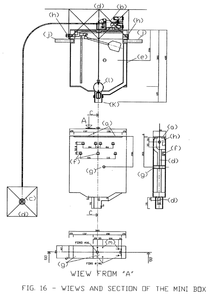
The FIG. 16 shows an installation example and building details of a mini box. The mini box differs from the recirculation plant here proposed but comes from the building details of the maxi box, from its actioning devices and from the plant camouflage. The mini box is the miniature of the maxi box: the details are identical as well as the gear device and the location of the anchoring sumps for the camouflaging piles._
Compared to the common flushing boxes it has the following advantages:
smaller overall dimensions thanks to the accessibility from the top that does not require holes on the front wall to install the actioning, inspection and maintenance devices;_
possibility of a complete camouflage back to the covering piles; possibility of installation in a top position allowing a higher discharge efficiency thanks to the gear devices;_
possibility of a double gear installation of which one is used for the total tank discharge (electric actuator) and one for the partial discharge: manual button (its release closes the discharge). Here follow the details of the figure. They keep the same identification letters in order to underline the similarity to the maxi box:
(a) removable cap in two pieces, kept in the seat with the anchoring clamps system fig. 9 (a) and the superior profile of the containing wall is similar to fig. 10 (a). We can notice that the mounting holes of the gear device are located on a cap. Inverting the position of the caps the device orientation can be changed as well; (b) electrical gear device; (c) manual actioning button; (d) removable piles; (e) overflow discharge incorporated in the tank structure; (f) anchoring
sump for pile support, fig. 10 (c); (g) connection reinforcement of the walls; (h) feeding connections of the
filling valve. In this case it is equipped with a gauge so that the overall dimensions are smaller in height compared to the diaphragm valve; (i) spherical shutter; (j) thread connections .” for support clamps in the wall; (k) bottom discharge.
The “mini box” does not follow the same logic of plant described. Its use has to be checked in the spread home plant engineering. The other components described and used in this project can find independent applications:_
(a) the recirculation sump can be used, as shown in the fig. 5, as a lifting sump for those places located under the roadway where a flooding danger can occur (basement recreation rooms, cellars, garages, offices, etc…) and needs a camouflage solution for aesthetic purposes;
(b) the ejector (fig._6) could be installed on all discharge sumps where the accumulation of sand, detergents and other substances causes a plague in the discharge: a periodical extraction through a special valve and the introduction of pressure in the water prevent expensive maintenance interventions;
(c) the maxi box (fig. 13 and 15) with the overflow valve mounted on the top through the special connection, can be used with the water system where a frequent interruption of water is expected; (d) the anchoring base for the pile holder supports (fig._9) covers the recirculation sumps as in fig. 5 and 6 and can be used to cover the common home sumps, allowing their camouflage with piles and substituting the common, unaesthetic metal plates spread in all homes.
Luigi Antonio Pezone