Vertical synergic buildings (VSB) for CO2 and water depuration plus biomass production.
N. Demand PCTIT2013000317 – International patent N. WO2014/076727
ABSTRACT
This invention is part of a group of inventions that aims to 1) prevent the phenomena of CO2 emissions which are the cause of global warming, 2) ocean acidification and the 3) recovery of the energy resources which are not possible with existing energy / purification systems. The most important invention is the one that brings together in a single system old and new purification systems and energy using technologies of the most advanced industrial and civil construction, so that nothing goes to waste in water and air. This main invention is called (GSPDPTC): “Global synergy for depuration plant, biomass production and thermoelectric cogeneration”, which along with another invention, called (GUED): “Global urban environmental depuration” provide total protection of the environment. Together, these inventions simply put together the plants in a rational way. This application (VSB) “Vertical synergic buildings for CO2 and water depuration plus biomass production”is one of the most important elements of the entire system. In fact, the (VSB ) should replace the existing large water purifiers, but they do so vertically, combined with the thermal power plants (TEPfos), and chimneys (CCPC) and large digesters dehydrators composters (LDDC). In (VSB) circulates all the water and fumes produced by the anthropogenic urban system and industrial areas and by different routes, the water cools the smoke, and subtracts the same CO2, SOx and NOx through greenhouses containing limestone (vcmlg) at the same time producing biomass from polluted water while purifying biological ponds in overlapping (bcsvp). But this production standard, also has options for terrestrial energy production: (vmcpg) “vertical mechanized production covered green house,” or water: (pbpma) “photobioreactors for the production of microalgae”. But to realize the entire system requires numerous other existing industrial technologies, which never entered into purification systems and energy. This is the reason why these vertical buildings are also called “synergy”. Only by putting together many technologies is it possible to close anthropogenic carbon nitrogen and phosphorus cycles. Current industrial systems cannot close these cycles, and as a result create the ongoing environmental crisis which plague the world today.
DESCRIZIONE
The technical field of this invention is environmental protection, the conservation of energy resources, the production of new clean energy. This invention belongs to a group of inventions that aim at preventing phenomena of water and atmosphere acidification and recovering of energetic resources, processes that cannot be carried out with current purification and energy production systems. The most important invention is the one that brings together in a single system old and new technologies so that nothing goes to waste. This main invention is named (GSPDPTC): “Global synergy plant for depuration, biomass production and thermoelectric cogeneration”. But to use the entire system there is need for many other existing technologies, in addition to those claimed. Only by integrating many technologies and many environmental applications it is possible to close anthropic cycles of carbon, nitrogen, phosphorous, recover and reuse the waste heat and CO2 in the environment.
The background art in the field of environmental protection and energy production, with the current planning methodology has ignored the possible synergies between the different systems that, if exploited in an integrated manner would lead to an efficient system of environmental purification (atmosphere and hydrosphere). Industrial chimneys are just a shortcut that doesn’t allow us to face or solve serious environmental problems since, from an environmentally aware perspective, the combustion cycles (irrespective of the fuel used) can’t be considered to be complete when harmful fumes are simply expelled into the atmosphere. Instead, the fumes should be transmitted to a further treatment stage to avoid the premature discharge of toxic and polluting substances into the environment and, at the same time, to try to recover wasted resources like heat and CO2. The current state of the art gives us a glimpse about technologically advanced solutions in the near future, such as the capture of CO2 from the environment through artificial trees, chemical or electrolytic alkalinization of large areas of marine waters or directly in the thermal power plants with Carbon Capture and Storage (CCS) technologies. Substantially, this last method, CCS concerns chemical washes that reduce the calorific power by capturing but not neutralizing the CO2: for this reason it’s necessary to compress, liquefy and bury it about a thousand feet deep through pockets that must be chosen carefully inasmuch as there is potential vulnerability as a seismic hazard which can result in dangerous gas leaks (the phenomenon called “Nyos effect named after the Cameroon village of the same name that suffered a catastrophic natural disaster of a large CO2 release which occurred in 1986). While Peak Oil theorists claim that petroleum is running out, the Oil & Gas industry is continually innovating new extraction techniques to extract energy sources which were hitherto inaccessible. For example, fracking has suddenly made shale gas accessible – reserves once considered impossible to reach. In March 2013, a Japanese team of drilling researchers announced successful extraction of methane hydrates from the ocean floor of the Eastern Nankai Trough off the coast of Japan. Although the Japanese government says that commercial exploitation is at least 5 years away, if successful, it is a game changer for Japan and the world because the U.S. Geological Survey estimates of known global reserves are between 10,000 and 100,000 trillion cubic feet of gas. To put this in context, US Shale Reserves are estimated at 827 trillion cubic feet. This amount is greater than all the oil and gas ever produced. For these reasons, it’s not likely that fossil fuels are going to be going away any time soon. Suffice it to say that were a large fraction of these reserves produced, it could prove impossible to stay below 2°C. At the same time, experimentally, the biological energy production is making great strides both with crops from the fields (with or without GMO’s) and with the production of algal biomasses. However, this type of production can’t become sustainable if the industrialization of production continues to steal valuable land required for agricultural food production. To avoid this resource competition, it is therefore necessary to find ways to scale production without competing with agricultural land. This means the use of agriculturally unproductive land or increasing production acreage by building vertically with industrial criteria. At the same time, we must also increase the production capacity of digesters which produce biogas and remove the source of CO2 content produced as a byproduct. In this context, whatever the energy of the future, whether it is traditional fossil fuel or biological energy production, the Vertical covered mechanized limestone greenhouse (vclmg) & photosynthetic greenhouse: vertical covered mechanized limestone greenhouse: (vmcpg) plus biological covered superimposed ponds plus (bcvsp) (pbpma) plus final biological covered superimposed ponds (fbcvp) incorporate in vertical synergic building (VSB) technology proposed in this patent application will authoritatively solve all the problems associated with purification of the fumes produced from the burning of fossil fuels meanwhile supporting the production of any type of energy, agricultural product or aquatic biomass. (VSB) alone cannot provide the solution but is a critical subsystem of a larger suite of new technologies envisioned by the applicant that when implemented together in an integrated fashion, will solve the major environmental problems facing the planet. VSB should be part of any major structural works including other existing works such as the TEP (Thermoelectric Power Plants), gasometer and other new works like the CCPC (Flue Gas Capture Cooling Purification Chimney) and LDDC (Linear Digesters Dehydrators Composters) which are subject of other PCT requests. The complete system envisioned to accomplish the task of clean energy production also requires the integration of other inventions of the applicant which will not have international patent protection, allowing other countries to copy these other designs freely. The usage of these international patents along with the applicants Italian-only patents will allow the achievement of other infrastructure able to receive these systems which increase the effectiveness environmental protection, both in the industrial and in the urban sector. These systems operate the best technologies in the following areas: energy, civil construction, industrial transport and storage, and food production in greenhouses and techniques purifying water and air. All current thermal power plants today follow an open loop industrial design philosophy and “end” with the current chimneys emitting untreated pollution directly into the atmosphere. The applicant’s inventions solves this problem by transforming the industrial process into a close-loop process that treats aerosol pollution and transforms CO2 into an environmentally beneficial product which is returned to the environment in the form of alkalized water. The CO2 captured at the source (in well designed thermal power) reacted and transformed in the VSB to produce benign and useful products, would become the main resource of global environmental protection. The VSB, along with its accompanying suite of other new technologies invented by the applicant, is co-located at the source of CO2 emissions; at the fossil fuel plant. This complete system will enable the VSB to capture the smoke stack fumes and treat them right at the plantsite. As part of its operation, the VSB also embeds facilities to filter large volumes of sewage water to use for the chemical reaction which depurates the fumes. In this way, the VSB depurates both air and water simultaneously. This total system, of which VSB is a key component, also recovers the heat and prevents SOx, NOx and aerosols from polluting the atmosphere. In summary, this system enables the production of fossil fuel energy or bioenergy while offering a complete solution to the depuration of air and water, purifying the water and preventing CO2, SOx, NOx, aerosol emissions at the same time that it treats ocean acidification. CO2 emissions from fossil fuel plants have two simultaneous negative impacts on the planet; global warming and ocean acidification. The increase of atmospheric CO2 from 280 ppm (preindustrial levels) to 400 ppm today has lowered the Ocean’s pH over 0,11 units that corresponds to an increase of ions (+) by about 35%. The applicant’s VSB accomplishes its principle task by enabling fossil fuel or bioenergy production whilst solving both these problems at the same time. VSB does this by consuming CO2 in an industrial process which accelerates limestone weathering to produce alkalized water transported into the oceans to counter the ocean acidification problem. It achieves this through an industrial process employing chemical reactions which, though long known by science and applied in various industries, have never before been brought together in an integrated industrial process to depurate air and water.
The applicant believes that the explanation of this phenomenon depends simply on the greater solubility of CO2 in water compared to oxygen and nitrogen, that arises due to its greater relative weight and as a result of Henry and Dalton’s Laws. Henry’s Law states that the mass of a gas which will dissolve into a solution is directly proportional to the partial pressure of that gas above the solution. Dalton’s law of partial pressures states that the total pressure exerted by the mixture of non-reactive gases is equal to the sum of the partial pressures of individual gases. The operating principle of the vertical limestone greenhouse is based on this reasoning. Many scientific texts report tables with the solubility of gases with respect to atmospheric pressure and at different temperatures: following publication are available on the net at: http://areeweb.polito.it/didattica/chimica. For example the rainwater, at the temperature of 30° C, contains, overall, about 15.89 cm3 of gas, which 10.38 cm3 is N, with small impurities of other gases, 5.26 cm3 of oxygen and 0.25 cm3 of CO2. While the CO2 fraction is only 0.25 cm3, if we consider that in the atmosphere it takes up a mole percentage of 0.039% only and that at the time of this patent application the mole fraction of CO2 was reported to be about 0.035%, we can easily calculate and demonstrate CO2’s far greater solubility in the ocean. Considering that N and minor gases fill 79% of atmosphere, we can compare the relationship between their volume occupied in rainwater and their respective rates in the air. This ratio, in case of N, amounts to (10.39 / 79 = 0.131) and in case of CO2 amounts to (0.25 / 0.035 = 71.14). This means that the CO2’s ability to solubilize in water with respect to the N, at atmospheric pressure, is effectively approximately 543 times higher (71.14 / 0.131). The same thing can be said about oxygen for which this higher ability to solubilize is about 285 times higher (5.26 / 21 = 0.25 then 71.4 / 0.25 = 285.6). This greater ability to solubilize offers an explanation of the planets acidification speed notwithstanding the rate is still low even though we can see it grow every year. This superior ability for CO2 to solubilize is exploited in the VSB to achieve environmental protection. Vertical covered limestone mechanized greenhouse VCLMG is a closed environment enclosing the saturated flue gases cooled by water with air vents placed only in the upper zone of the chamber. The CO2 diffuses to entirely fill both the space reserved for the gas in the large volume of water collected by the open water basin at the bottom of the reaction chamber as well as the low-lying portions of the reaction space while nitrogen and oxygen will rise much faster in the internal atmosphere. This condition of saturating the space surrounding the suspended calcareous materials accelerates the process of corrosion hundreds of times as if we had pressurized the VCLMG chamber with many bars of pressure or cooled it down many degrees. However, this greater solubility is temporary and depends on the artificial conditions created by channeling large volume of CO2 from flue gas into the space of the reaction chamber. When waterleaves the space, nitrogen and oxygen will occupy again their natural space and CO2 will be returned to the atmosphere. To allow CO2 remaining in the water stably even when it get out from the enclosed space of the reaction chamber, it’s necessary to turn it in to bicarbonate or carbonate. For these reasons VCLMG’s sections are designed: they ensure the contact between the crushed limestone material, water and Co2 renewing the consumed material by scheduled expirations so that the ion exchange always takes place with maximum efficiency. It’s clear that the environmental conditions created in a VCLMG with high concentration of CO2 made by thermal plants, with the cooling of the flue gas due to a greater amount of water used in the process and with the multiplication of the contact surfaces due to rock crushing that, in any case, must be broken to insert them in ovens, all this allows obtaining a cold carbonation of rocks and alkalinizing ocean waters. The weathering of limestone is the system which nature herself uses to keep the oceans slightly alkaline and prevent ocean acidification, and the design submitted here by the applicant is simply a way to accelerate and scale that same process to handle New industrial plants should be designed differently, to mimic natural processes which are closed-loop cycles. The new designs should be an integrated one that combines energy production with environmental depuration in a synergistic, cradle-to-cradle system that recycles all waste back into useful industrial feedstock fed back into the same plant. It is these open-cycle, linear designs that currently mine valuable resources from the lithosphere then inject them directly into the atmosphere and hydrosphere where they cannot help but take on the role of pollutants. By building these new integrated plants, we close the anthropogenic carbon loop, transforming what were formerly considered “waste” products of the old industrial paradigm back into useful feedstocks in the new industrial paradigm which produce outputs which are both useful to human civilization and benign or beneficial to the environment. In this way, we have a logical way to create large scale zero waste industrial systems. If any large scale plants which currently burn fossil fuel are efficiently paired with CCPC (capture cooling purification chimney), VSB (vertical synergic building), LDDC (linear digester dehydrator composter); gasholders and to the amount of water needed for cooling, we can close the anthropogenic carbon and water cycles to achieve zero waste. Therefore, by using this new global depuration paradigm, it is possible to prevent harmful industrial emissions from polluting the environment, to significantly increase the energy production efficiency of each plant and to produce a product which remediates acidified oceans. To increase its economical viability, it is critical to pair every such plant with an LDDC that can recover the tremendous amounts of heat energy lost in the ubiquitous and inefficient steam turbines to produce and use it to produce significant additional amounts of bioenergy. The cost gap between fossil and biofuels is eliminated by the superior performance of the new integrated plant system. Some major outputs, such as the alkalized water for treating acidified oceans, do not even have a price associated with it yet. The LDDC can produce either bioenergy or compost or any mix thereof. Although a number of interesting bioenergy pilot plants have been built around the world, biofuel production still has not scaled to meet its promised potential particularly microalgae biofuel production which has an output ten times more efficient than cereal crops yield. Large scale bioenergy production is hampered by a number of factors including: the artificially low cost of fossil fuels; lack of global enforceable environmental laws or regulations on combustion fumes and heat recovery; low Energy Return On Investment (EROI); ineffective plant designs which generate relatively low amounts of power; poorly designed digesters which are bulky and smelly and competition for agricultural land. It is becoming increasingly clear that the planet is threatened by the climate change policy gridlock resulting from the power and entrenchment of the fossil fuel industry. Institutional investors are being encouraged to stop funding fossil fuel energy projects because the exploitation of all the known reserves will propel global temperatures far beyond the safe 2° C limit. Yet, fossil fuel companies continue to ignore these findings and open up new and controversial areas such as fracking, methane hydrates or drilling in the Arctic. The fossil fuel industry is fully aware of the divestment strategy now taking place but appears to be disregarding the research results of climate scientists and economists and risking an uncertain future for humanity. The system proposed in this patent, if fully and globally implemented has the ability to offer a way out of this difficult problem. By eliminating CO2 and aerosol emissions from all static fossil fuel combustion processes and solving the ocean acidification problem caused by the same emissions, this design offers an attractive alternative to stakeholders of fossil fuel combustion plants. It allows them to continue exploiting cheap, high energy density fossil fuel energy source without polluting and buys time for alternative renewables to scale. Furthermore, with the addition of algae photobioreactors, these new plants can in fact become pure, autonomous bioenergy plants capable of producing energy in the same scale as existing fossil fuel plants. This futureproofs the investment which is originally developed for fossil fuel sources because it allows autonomous energy production in case of peak oil. This system which removes CO2 also performs an ion exchange with calcium, manganese and silicon content in the VCMLG’s stored material transferring the carbonates salts in the water. Of course, it can’t happen whether it continues to build thermal high power plants without worrying about the carbonates quantities that water can move. And despite the state of the art has experience about efficient systems capable of reducing particulate matter, SOx and NOx, these substances are forced to react with calcium to produce sulfates and nitrates which add themselves to carbonates made by CO2. Naturally, this solution isn’t suggested. The filtration is the best way and, without it, it’s better to have sulfates and nitrates in the water rather than in the air. This is because the water that collects in the basin of water to be alkalized (wba) endures a valid oxidation treatment inasmuch it is raised and then made to fall through the rocks but, if it’s particularly polluted, it can be traced back more slowly through adjacent sections where, as you can see, there are BCSVP (biological covered superimposed ponds) in which water is purified as it rises upward and purification can be accelerated by circulating ion exchange resins mechanically.
The disclosure of this invention is basically divided in two parts illustrating: 1) the fumes’ depurative process and 2) the waters alkalization made in limestone greenhouses, while the water depuration and biomasses production occur in the photosynthetic plant sections. Obviously, the description is very wide because it combines several natural processes and industrial technologies that have never before existed in the depurative sector. The current depurative systems are primitive in their environmental protection function when compared to VSB which operates in closed-loop cycles to make use of waste material and energy to effectively treats both water and air. Polluted waters, polluted air, liquid digestate, heated waters constitute the waste material and energy streams used as feedstocks to produce depurated, alkalized or desalinated waters and more terrestrial and aquatic energetic biomasses sent to digesters, dehydrators and composters LDDC. In particular, it is possible with this new design to realize plant synergies which can better exploit both Dalton’s Law of partial pressure of gases and Henry’s Law of gas solubility in water that, as reported above, lead to unimaginable increases in water and air purification performance.
Fig. 1 and 2 describe a VSB system producing biomasses and purifying and alkalizing waters. The system can also be configured to desalinate water by circulating ion exchange resins in the BCVSP’ ponds (biological covered superimposed vertical ponds). Therefore it’s possible to create a system producing exclusively aquatic biomasses or one that produces terrestrial ones by reducing the space occupied by sections (bcvsp) and filling the subtracted volume with topsoil and compost, turning this section into VMCPG (vertical mechanized covered production greenhouse). Naturally it’s necessary to also add the transportation system and the mechanical working of the soil. In the same space, it is also possible to overlap the depurative aquatic biomasses production in (bcvsp) and, above it, install the PBPMA (photobioreactors for the production of microalgae). Doing this must be accompanied by improvements to the natural lighting by the addition of artificial LED or other lighting. All these systems would work by the reuse of resources that today are wasted and released into the environment – like the heat content in waters and rivers, the CO2, organic nutrients, phosphor and the nitrogen content in polluted waters. Biomass production is currently developing separately in labs,industrial plant and in many agricultural greenhouses all around the world but, once transferred to the environment of the VSBs, they can find, in one place, ideal components for optimal growth.
Production of terrestrial biomasses. In this invention we take mature greenhouse technology available today and adapt it to the novel vertical building structure of the VSB to save on valuable land resources. Along with the capture and reuse of industrial volumes of waste heat and wastewater, this system recycles water and avoids groundwater pollution. For this type of crop, we can apply the techniques used in rooftop gardens (posing the soil of crawl spaces in plastic material covered by non-woven filter) to transform these into the sections vertical mechanized covered production greenhouse (vmcpg). Vertical greenhouses have obvious advantages of multiplying the normal growing areas by the number of floors in the structure and using existing grow technology with productivity greater than 50%.
The recovery and purification of wastewater within the VSB significantly lowers water consumption and produces little or no pollution. But it is especially interesting the Production of algal biomasses. Even in this case we don’t claim as our invention agricultural crops in photobioreactors that is a consolidating technology, but only the verticalization of these in order to obtain an industrial development which can save resources to ambiences heating and water consumption resetting groundwater pollution by the water recycling and providing raw materials for the production like nutrients and the CO2 captured from thermal plants fumes. Photobioreactors for microalgae production, most likely for energy, outstrip agricultural production, which also agree cultivate in VSB for food , humans and zootechnic, especially when the power plants will be fueled with bio-fuels completely and will not contaminate by unwanted substances. These buildings can serve both for the production of energy and food production (preferably in separate VSBs) purifying the water and the air as either is produced. Research with micro-algae grown in photo bioreactors have demonstrated tubular productivity of biomass energy of about 15-25g / m2 per day of surface exposed to light. The photobioreactors consist essentially of a set of tubes of plastic or glass from the small diameter ( 0.1- 0.2m) to limit dark areas inside. The biomass inside these tubes are moved by small mechanical pumps. There already exist methods for the automatic cleaning of the tubes when it becomes opaque due to deposits on the walls. The oxygen generated by photosynthesis (up to 10g * m3/min with maximum light) must be removed or it will cause photo oxidation that affects the productivity. It is therefore necessary to implement a degasser to strip the O2 from the air. It is reasonable to assume a path of 80m max. before the biomass returns to the removed oxygen. An airlift pumping system is suitable for this purpose: the air is fed to the base of the riser pipe along which the O2 produced by photosynthesis is stripped. The stripped gas is released in the riser head, which is, generally, where the removal of the produced biomass occurs. CO2, with a utilization efficiency of around 80% and which enhances algae growth, enters at the base of the descent tube of the cultivated broth. If such a system of biomass production is integrated into VSB,, the optimal source of the concentrated CO2 that will feed the photobioreactors is that which occurs near the surface of the water of the basin ( wba ).
The concentrated CO2 drawn from water surface of (wba) can be further enhanced through other exsisting technologies. In fact, The concentration process generally consists of an adsorption system, that most of the time using amines of any type (10-40 % concentration in water). The raw gas, which is close to room temperature, enters into an adsorption column, where the gases are countercurrent amine poor. The carbon dioxide adsorbed by amine becomes enriched amine, and the rest of the gas, typically nitrogen or synthesis gas, are dispersed in the atmosphere. The enriched amine is heated in a heat exchanger, before it reaches the desorption column. In this column, a kettle further heats the amine to about 120° C, in order to desorb the carbon dioxide. The desorbed amine is recycled back into the adsorption column, having been cooled by enriched amine coming from the adsorbent. The hot carbon dioxide leaves the desorption column and is cooled with water and sent to the main system to be liquefied and purified. The basic procedure consists of compressing the raw gas to enable it to overcome the pressure drops at different stages of purification. Once dried and free from heavy hydrocarbons, it is liquefied through external or NH3 refrigerant (freon) and being non-condensable, are eliminated in a special packed column. Finally, the gas is subcooled and stored in insulated tanks at low temperature. In order to achieve the required pressure (generally from 16 to 25 bar) in a cost effective manner that liquefies the purified carbon dioxide gas, two stages of compression are required in order to protect the compressor. It is necessary to remove the maximum amount of moisture. A separator, provided with a special automatic valve, controlled by a level transmitter operated on a solenoid valve, drains the condensed product. CO2, with a concentration of 98-99 % is then distributed to various photobioreactors (pbpma) that will occupy the space available above the (bcsvp).
Current water treatment plants consume energy and emit CO2 while the VSB purification process produces biomass for energy production which absorbs CO2 as is summarized in the following formulas: C6H12O6 + 6O2. ↔ 6CO2 + 6 H2O + approx 38 molecules ATP
which is the reverse of photosynthesis, which consumes CO2 instead:
(6 CO2 + 6 H2O + 2872144.8 (j / mole) ↔ C6H12O6 + 6 O2. Even in the basins (wbp) of VSB are oxidized, CO2 but it is not expelled into the atmosphere, rather it is consumed as a valuable resource in the same system. To transform a VSB which alkalize the water in a desalination that, just use the links (aws), alkaline water supply, and (wss), water sofned supply, between the basins (wba and wbp), and strengthen the purification process by deleting the sections of mechanized production (vmcpg) and expanding those with water (bcsvp) complete of resin wheeled hanging baskets (rwhb), with synthetic resin ion exchange.
It describes the fig. 1: The unpolluted waters, to alkalize or desalinate together with the cooling water of thermal plants arrive in the basin (wpb), while the polluted sewage, agricultural land industrial water arrive in the basins (wpa) where it undergoes an oxidation treatment with air diffusers fed from (efa). In this basin the surface of the water can be lit with “LED” grow lamps to exploit the effect of photosynthesis. The sludge produced by this process are raised by pumps (slp) to tanks (ttst), transit tank sludge to be thickened, whose overflow, the lightest water, is returned to the basin of water to be purified (wbp). The sludge thickened by the hydrostatic pressure feed (tsh), thickened sludge hopper. The waters, taken below the cloth plant, are raised, as they arrive waters (after the signal level in the tank) on the first floor of (bcsvp), biological covered superimposed ponds; in which, the level reaches the maximum to 100 cm, is to offer a greater surface area to the light, with equal volume stored, both to reduce the hydrostatic pressure on the walls of the building. Each pond keeping constant their level, without overflow raises the water to the next floor when they get water from downstairs. In biological covered superimposed ponds (bcsvp) cultivation of aquatic plants superficial type azolla or duckweed, is a cloth uniform surface preventing the proliferation of algae, while the submerged transit of the baskets (whose ionic resins arerenewed daily) removes the soluble salts in the area below. This also happens for the third, fourth, fifth floor, up to the top floor final (fbcvp), final biological covered vertical pond, where the water is purified by the various synthetic steps and photos from ion exchange resins contained in hanging baskets. If the water is purified and demineralized to the programmed level, as measured by sensors and probes to control dissolved oxygen, salinity and pH, the water then overflows; withdrawn below the surface layer by means of an immersed baffle, is discharged through the (pwdv), purified water drain valve, otherwise it is discharged through (rwv), recirculating water valve, that feed (wot) water overflow trays. The (wot) are also fed by rainwater collected from the roof of the building (plv) and above all, by the waters raised by lift pumps (wlp) of the water basin to be alkalized (wba). If the system will also be used to desalinate seawater and brackish water, these will come in the basin of water to be alkalized (wba). The waters in this basin, which is only to be alkalized, whether they must be softened or not, are raised directly to the overflow (wot), while the tap water that you make in the basin (wpb) will be brushed up, along with those oxidized to biological ponds (bcsvp). The waters that reachpans (wot) will fall like a torrential rain onto baskets filled with limestone boulders lined up in the overflow trays. Since the environment the limestone boulders are suspended in is rich in CO2 coming from the fumes captured from the chimneys, fireplaces and the exhaust gas, the resulting cold carbonation reaction will extract from the rocks their respective ions: Calcium and magnesium ions: CaCO3 + CO2 + H2O ↔ Ca2 + + 2 HCO3-; for dolomite: CaMg (CO3) 2 + 2CO2 + 2H2O ↔ Ca2 + + Mg2 + + 4HCO3 and, to a lesser extent, this also applies to the ions of the other most common minerals (Na +, K +, Cu + +, Ni + +, Pb + +, Zn + +, etc). The ionized water will fall into the basin of water to be alkalized (wba) where it is collected for later reuse. Being impure rocks, the dripping of dirty water which can be a mixture of clay, crushed stone, calcium, silicon and various minerals are collected in a removable double bottom of the (cwhb), calcareous wheeled hanging baskets, covered by a fabric filter panel, which passes only alkaline water. This avoids pollution of the (wba) and limestone can easily be integrated from the top of the basket removing, cleaning and replacing the filter removable bottom. The water falling on the roof in the slope (wba) is conveyed laterally through a (csc) collecting stones channel, protected by a small grid. In this way even the few stones falling from the top can be consumed without producing unwanted sludge in the basin of water to be alkalized (wba). The channel (csc) is covered by the rain that falls from the top to divert the flow of rain on the floor and forces the impurities to settle in the channel, which is cleaned by a hanger (emr), equipped and motorized rak, with a rubber shoe. From the channel (csc) is taken alkaline water (aws) that feeds (wbp). Note that in the greenhouse limestone environment, the fossil fuel plant fumes which arrive contain about 10% by weight of air (250 times higher than the normal concentration in the air). Since CO2 is 1.5 times heavier than air and furthermore, there is no wind in this environment, we have a stable CO2 concentration which is effectively hundreds of times higher than atmospheric. Consequently, by Dalton and Henry’s Law, the specific pressure of this gas in the air is hundreds of times greater than normal atmospheric conditions while the CO2 content in the drops of water that cover the rocks and penetrate into the microcracks is tens of times above normal atmospheric conditions. This effectively allows the CO2 to displace the nitrogen and oxygen in the air mixture, effectively occupying the space normally occupied by nitrogen and oxygen. The calcareous rock or rubble suspended in the baskets are broken into small pieces so that the exposed surface area is a few hundred times higher than that normally exposed in underground limestone stalactite caves. Subsequently, the removal of calcium and magnesium ions is hundreds of times faster than the natural processes occurring in these caves. Therefore, both the alkalization of freshwater and salt water softening, can benefit from this well known process. In the system herein described in this patent, the applicant’s invention exploits these natural processes and accelerates the weathering so that they can apply on an industrial scale and time frame. The storing and transport of mechanically crushed rocks, and designing plant synergies that increase yields enables the design to purify industrial quantities of CO2 from the air in real time. It’s very easy to get in (wba) to a critical pH (9.5 to 10) which precipitates the calcium and magnesium on the bottom of the basin in the form of calcium carbonate and magnesium, according to the reverse reactions to those above. Extracting the sludge, and then the carbonates we find in the waters a greater amount of carbonic acid (HCO3-) in the environment which liberates the CO2 unsolved, that in (vmcpg), mixing again with water and limestone rocks free from other ions calcium and magnesium, which will create new bicarbonates in the basin of water to be alkalized (wba), up to reach again the critical pH that makes them fall. Using this system we do not need other systems to consume the CO2, alkalize or sweeten the waters.The sea salt cannot be eliminated, but the CO2, photosynthetic partially transferred into the greenhouse by means of electric fans (efa) allows us to produce their biomass at the expense of these salts. We must not forget that in order to produce simple plant molecules are required immense amounts of components: “every 35 million carbon atoms from the photosynthesis takes 30 million atoms of oxygen, hydrogen and 60 million well-1.552.904 Atoms of different elements made from the water (nitrogen, potassium, calcium, magnesium, phosphorus, sulfur, iron, boron, manganese, zinc, copper, cobalt, molybdenum). Therefore, in the ordinary urban environment, depuration minimally requires a VSB which consists of: a number of adjacent vertical limestone and photosynthetic greenhouses, access to urban water and well-place the air cleaners without leaving the city and also allowing air purification. To purify large concentrations of pollutants such as liquid digestate or to desalinate large flows of brackish or sea water requires integration of the appropriate technology, which in the case of VSB is ion exchange. Millions of cubic meters of water may exist at any one time in the various sections of a VSB (wbp, wba, bcsvp. and fbcvp which may be circulating at thousands of m3 / h. The system for purifying the water is similar to the one already used for moving the baskets of calcareous material around the VSB. In the same way perforated baskets on an automated conveyor system is used to move ionic resins through biological ponds of water to be treated. (bcsvp and fbcvp) These ponds also integrate photosynthesizing plants that are active in the surface region. If this system is to be used for the desalination of sea water, it will be necessary to induce the precipitation of carbonates. The water will rise to the reservoirs (wba) in dry oxidation (wbp) will be acidic and rich in carbon-free salts. These will be neutralized in (bcsvp and fbcvp) integrated with the exchange resins contained in (rwhb), resin wheeled hanging baskets. Alkaline water supply (aws) that will take relief from the channel (csc), will contribute to the normalization of altered PH in the basin of water to be purified (wbp) before it falls in the basin of water to be alkalized (wba). The arrival of the new salt water in (wba) continues to feed the process via (wbp) via the connection (wss). This connection will be closed if only fresh water enters (wba). As new water arrives, it raises the level, regardless of the degree of purification achieved, the force (wbp) to raise the excess water to the upper floors of the (bcsvp). As the water flows through and rises to the consecutively higher ponds, it becomes less and less rich in salts, until reaching the level (fbcvp), the control probes salinity, dissolved oxygen and pH, ensure that it has reached the necessary parameters and allow the opening of the (pwdv) purified water drain valve, closing the recirculation (rwv). The ion exchange inserted in (bcsvp and fbcvp) is a ‘reversible interchange of ions that occurs between a solid substance (resin) and a liquid not altering the structure of the solid. The principle of ion exchange, is validly used in the treatment of wastewater for the removal of waste nitrogen, heavy metals, dissolved solids.
The ion exchange resins are of the conventional organic macromolecules formed from a polymer matrix suitably cross linked so that it is able to fix ions. There are specialized resins for all depurative applications. They are marketed in the form of small spheres with diameters and uniformity depending on the type of application, having a diameter of between 0.3 mm up to 1.2 mm. Although the rate of ion exchange is inversely proportional to the square of the diameter of the particles, for the application in baskets, the tradeoff will be to employ the larger diameter. The ion exchange process takes place in two phases: an operating phase and a regenerative phase.
Phase 1, Operating Phase: Ionic resins are immersed in ponds, suspended to the carriages and enter one side of the pond , travel through it and finally exit from the opposite side of the pond. The various floors of the sections (bcsvp), in the part concerning the ionic exchange, will be either be cationic or anionic. The amount of resins contained in the baskets are proportional to the content of salts that must absorb. In this way the water that rises upward through both sections that those cationic anionic while the resins are renewed separately without creating turbulence in the ponds.
Phase 2, Regenerative Phase: It follows the operating phase and consists of replenishing or recharging the active sites of the resin for later reuse. This regenerative phase is carried out on the ground floor of the VSB by dragging automatic trolley baskets through tunnels designed for cationic or anionic regeneration. The regeneration process is divided, in turn, in three sub-steps:
a) Initial drying serves to remove the impurities deposited on the drum that prevent the passage of water and the regenerating solution. High pressure jets of demineralized water is sprayed from above. The action of the jets cause the automatic aperture of the lid to tilt, allowing water to penetrate inside the baskets.
b) The regeneration takes place by immersion in the next tunnel, the length of which is calculated based on the time required. This can be acidic or basic depending on whether it is a cation exchange resin (with HCl, H2SO4), or anionic (NaOH) one. Dilute solutions are used where the proportion of acid or base dissolved depends on the strength (degree of dissociation) of the same.
c) Final washing is performed to wash away the residual acid or base and also occurs automatically in the tunnel with jets of deionized water which is sprayed from above to penetrate into the baskets. This is finally followed by soaking in a bath of deionized water. After this step, the initial working conditions are re-established.
The logistics of VSB. From the FIG (1) and(6) environments (vmcpg and bcsvp) are arranged laterally to the central limestone (vclmg) to take advantage of natural light, appropriately supplemented with artificial light. The covers of (bcsvp) will consist of gratings with large voids to allow the passage of light. Both sections will exploit the heat from the (hwt) hot water tubs and the proximity of the section (vclmg) from which it will pick up warm, moist and CO2-rich air, blended with outdoor air in special(air handling units (uta) and controlled by humidity, temperature and CO2 sensors in the environment. This will create optimal environmental conditions for the production of agricultural biomass and water throughout the year, taking advantage of the carbon due to CO2 fertilization. In the Vertical Synergistic Buildings (VSB), mechanical handling and storage baskets (cwhb and rwhb) and equipped and motorized racks (emr) are used for tillage and harvesting. We can realize the VSB with varying degrees of automated moving baskets and racks, suspended carriages which are either motorized or manually pushed from one floor to another and from one lane to another, following predetermined paths with longitudinal, horizontal or vertical translational motion. These automated handling systems are commonly found in other industries such as automobile or other manufacturing. Moving through translational and lifting the sections of track that carry the motorized carts and not, who are suspended racks and baskets. The equipped motorized rack (emr) will be equipped for the processing surface of the terrain, for planting, cutting, chopping and the aspiration of the fine, the cleaning of the channel (csc). Since the energy production very simple from the point of view of the working, the energy production can take place fully automatically: the harvest, shredded aspirated, through channels suction side to the race of the hanger, is sent to the storage silo of biomass (sbm). The automated handling system moves the baskets (cwhb and rwhb) and hangers (emr) through the stations on the ground floor, where they are cleaned, refilled and maintained (including the replacement of the batteries DC of (emr)). Ion exchange resins are washed and recharged at stations located throughout the path. At the end of the relative paths, baskets and racks are inserted in (brse), baskets and racks sorting elevator that operates outside the structure of the building. The elevators can stop at any floor to insert or draw the baskets, or the suspension bars. Hinged, rubber-sealed doors minimize the loss of heat and CO2. It is not necessary to electrify the entire path, – only the sorting section on the ground floor outside of the greenhouses by means of exchanges, descenders / elevators and hoists. Being long paths and not continuously used, it is only necessary to motorize the transport carriages of the suspension bars and agricultural equipment which have DC motors which are powered by interchangeable batteries. (battery charging stations will be conveniently located on the ground floor).Also the pneumatic transport of fine has been widely tested in industry, while for the suction of the chopped biomass by the moving hanger, we can adapt the suction systems used for the extraction of welding fumes in the work stations in movement: provide a vacuum collector, equipped with a slit covered with rubber lips that open to the passage of the metal terminal shaped suction pipe connected to the suction and chopping of the crop. There is no need to power the trucks that support the baskets with limestone boulders and ionic resins. These will be operated as in a warehouse: entering from one side of the greenhouse and out the other, pushed from behind by the trucks to come in and dragged by forklifts for output. Indeed, the trolleys will be equipped with spacer bars which engage between them automatically during loading and disengaged during output, when the extractors of hoists include them in the translation rail.
Brief description of drawings. Before proceeding with the description it is considered appropriate to report a legend of the symbols used in the description and the annexed drawings:
Legend: (ac) air compressor; (af) air filter; (ags) agitator sludge; (ahu) air handling units; (aid) air inlet dampers; (aout) air outlet; (acwhs) arrival cooling water heating system; (apt) atmospheric pressure tank; (art) anionic regeneration tunnel, (as) arrival sewer; (asc) anaerobic sludge collector; (assc) anaerobic sludge submergible collector; (avhe) heat ewchanger; (agrw) agricultural wastewater; (aws) alkaline water supply; (bcf) biogas cyclone filter; (bc) bagged compost; (bcsvp) biological covered superimposed ponds; (bmh) biomass hopper; (bms) biomass silo; (bioc) biogas collector; (brse) basket and racks elevator; (bws) boiler water supply; (casrb) covered area sorting racks and baskets; (ccc) central covered channel; (CCPC) capture cooling purification chimney; (cf) cyclone filter; (cd) conical diffuser; (clp) condensate lift pump; (CMCO2) collector transport compressed mixture of air and CO2; (cr) carriage road; (crt) cationic regeneration tunnel; (csc) collecting stones channel; (ct) condensation tank; (cwhb) calcareous wheeled hanging baskets; (cwlp) cold water lift pump; (cchwf) covered channel for hot water and fumes; (cws) cold water supply; (db) domestic boiler; (dlh) digester loading hopper; (dp) dewatering pump; (dst) detergent solution tank; (dwb) downstream water body; (dst) distribution smud tank; (dw) depurate water; (dwt) desalinated water tank; (ebCO2) electroblower for CO2; (ebbio) elettroblower for biogas; (efa) electric fan for air; (eff) electric fan for fumes; (esf) electrostatic filter; (emr) equipped motorized rack; (ethw) espansion tanks for hot water; (etcw) espansion tanks for cold water; (fai) fresh air intake; (fcv) flow control valve; (fvhe) fumes vapor heat exchanger; (fgec) flue gas expansion chamber; (fgwe) flue gas water exchanger; (fbcvp) final biological covered vertical pond; (fgfs) flue gas filtration system; (gas) gasometer; (gf) grating floor; (GMLED) global marine and lacustrine environmental depuration; (GUED) global urban environmental depuration; (gw) glass wall; (hwb) hot water basin; (hwp) hot water pipes; (hwcb) hot water covered basin; (hwcp) hot water circulating pump; (hwfc) hotwater and fumes channel; (hwlp) hot water lift pump; (hws) hot water supply; (lf) lower floor; (lbh) limestone boulders hopper; (LDDC) linear digester dehydrator composter; (ls) lime silo; (mgg) mini glazing greenhouse; (pbpma) photobioreactors for the production of microalgae; (pcbio) pneumatic conveying biomass; (plv) rain; (pfb) public facility boiler; (pvum) purifying vertical urban module; (pwdv) purified water drain valve; (pwo) purified water outlet; (rfwt) resins final washing tunnel; (rm) removable cover; (rcpld) road control panel with mini limestone dosing hopper incorporated; (rrpwl) recovery rainwater and purified water line; (rsiet) regenerating solution ionic exchange tanks; (rrt) resin regeneration tunnel; (rwt) resins washing tunnel; (rwv) recirculating water valve; (rww) resins washing water; (rwhb) resin wheeled hanging baskets; (se) stairwell and elevator; (sfgc) settling flue gas collector; (sh) sludge hopper, (sk) skylight; (sid 1-2) smoke interception damper; (sle) sump sludge extraction; (slp) sludge lift pump; (sov); shutoff valve; (spas) submersible pumps for anaerobic sludge; (ssl) settler in sewer line; (STAMCO2) storage tank atmosferic mixture of air and CO2; (STCMCO2) storage tank compressed mixture of air and CO2; (stt) sludge tape transport; (tsp) transparent solar panels; (ttst) transit tank of sludge to be thickened; (rwv), recirculating water valve; (TEPbio), thermoelectric power plant fueled by biogas; (TEPfos) thermoelectric power plant fueled with fossil fuels; (tucCO2) thickening CO2 underground collector; (uf) upper floor; (upwb) upstream water body; (uv) unidirectional valve; (vcmlg) vertical covered mechanized limestone greenhouse; (vahe) heat exchanger; (vm) vertical mixer; (vmcpg) vertical mechanized covered production greenhouse; (VSB) vertical synergic building; (wb) water body; (wba) water basin to be alkalize; (wbc) water cooling basin; (wbp) water basin to be purified; (wlp) water lifting pump; (wfd) washing floor drain; (wodc) water overflow and drainage channel; (wot) water overflow tray; (ws) water supply; (wss) water sofned supply.
Drawing “1/6”: fig. (1) is the flow chart VSB purifier water maker and producer of biomass. We can see the central side of the scheme made by the basin of water to be alkalize (wba) where clean waters arrive to alkalize. Above it there’s an intermediate floor above it again there’s the mechanized calcareous warehouse (vcmlg). Above it there are the (wot) (water overflow trays). It’s possible noting that the flue gas containing the CO2 is entered below the roof slab of the (wba) and the air, to reach the exit at the top, is enforced to do a quite tortuous path and at the end it has to pass through the baskets containing calcareous materials in the rain caused by the water overflow trays (wot), Fig 2 shows that in the same space occupied by biological ponds (bcsvp) we are able to produce micro algae. In fact, due to limited space in height (bcsvp) and the fact that it does not require mechanical work but only of light, we can superimpose to it (PBMA) (photobioreactors for the productions of microalgae) entirely suspended from the ceiling, to leave free the floor, beneath which can circulate (cwhr). You can also see the various flows of water and air. And above all, that the air can have several entrances but can only come out from the top of the greenhouse.
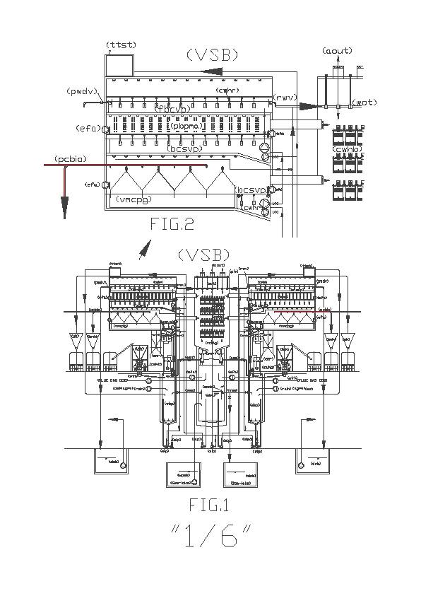
Drawing below is the longitudinal view VSB, where you can see the area on the ground floor with the transit of baskets (cwhr) and (cwhb) and superiorly, purifying the area and production of biomass. Notice that (bcsvp) biological superimposed covered ponds are always present, although the narrow version, when combined with (vmcpg) vertical mechanized covered greenhouse production; You can see the two head of the building (brse) basket racks and elevator, without which it is not possible to realize the industrialization of environmental protection. Located on the roofs of the buildings are transparent solar panels. Fig 4 is the magnification of the work area on the ground floor.
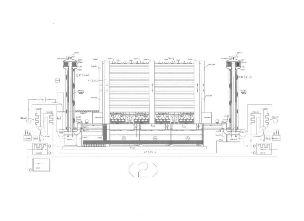
Drawing below is the diagram of a vertical purifier global industrial in which are inserted VSB together with other industrial installations: 1 (TEPfos), 2 (CCPC fos), 3 (VSB), 4 ( LDDC), 5 (TEPbio), 6 (CCPCfos). Where (TEPfos) produces fossil energy, heat, fumes and CO2; transfers the CO2 and the heat of the fumes to (CCPCfos), while the heat content in the water goes to (LDDC); (CCPCfos) transfers the heat to (LDDC) and CO2 to (VSB). This produces biomass, which transfers (LDDC ) and alkaline waters that sends to the seas; (LDDC) produces biogas, which transfers (TEPbio), solid digestate for agriculture and the liquid digestate that moves to (VSB), while the hot smoke with CO2 ranging in VSB. Meanwhile (TEPbio) produces biological energy, heat, fumes and CO2; transfers the CO2 and the heat of the fumes to (CCPCbio), while the heat content waters goes to (LDDC). The cycle can continue indefinitely coexist in the same system as fossil fuels and organic which together produce clean energy, compost for agriculture and alkaline waters to combat ocean acidification. But (VSB) with different management can also desalinate sea water. Many technologies come into this system, the applying claims only (CCPC), (VSB), (LDDC), (GSPDPTC).
Drawing “4/6” fig. 6, transversal section, views of a global industrial sewage treatment plant, where it shows the connections between the air and underground buildings (VSB) and (LDDC).This drawing shows the silo of biomass (bms) and calcium oxide (ls), the bags with the draining compost (bc), the link between the limestone section and the digesters, the chamber containing biogas with the water basin to alkalize (wba) for the CO2 stripping, and air composting and dehydration always with same basin (wba) which does not broadcast outside odors. All aerobic processes of the building (LDDC) reach the atmosphere passing through vertical synergic building (VSB), in particular limestone section (vcmlg) and exits into the atmosphere (aout). The water contained in hot water pipes (hwp) will contribute to warming and drying of the greenhouses (bcsvp), (vcmpg), (pbpma) and will end in the water overflow trays (wot) on top of the limestone greenhouse
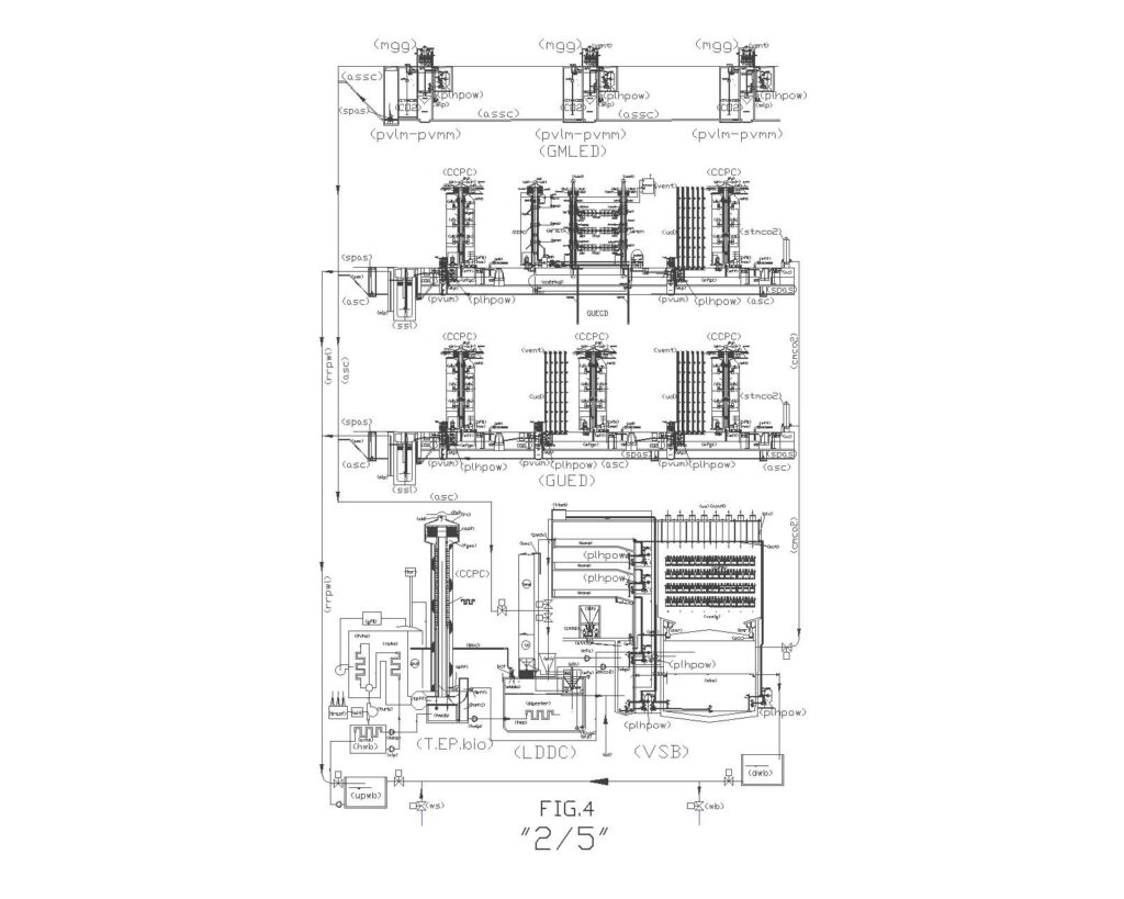
Drawing Fig.4 shows the scheme of (GUED), “global urban environmental depuration” and the scheme of (GMLED) “global marine and lacustrine environmental depuration” integrated in the system GSPDPTC, described above, that have been invented later, in which there are the urban version of: 1 (CCPC), 2 (VSB), 3 (LDDC), 4 (TEPbio) for application in urban environments that produce fossil and bioenergy, heat, smoke, CO2 and polluted water. The heat of urban (CCPC) goes to (db) domestic boiler, the heat of urban (TEP) and its (CCPC) goes to (LDDC); urban CO2 from the TEPs and (db)s goes to (VSB). (VSB ) produces biomass, which is transferred to ( LDDC ) and alkaline water that is sent to the sewer system, which will be very different from the current system because it does not produces hydrogen sulphide, but purifies the water and capture CO2 and smog. In the same figure is too reported the marine and lacustrine application using the same (pvm) with a different composition. (LDDC) produces digested solids and liquids, as well as biogas that is transferred to (TEPbio). The digested solid is used for agriculture while the digested liquid is transferred to (VSB). This loop can continue indefinitely with a coexistence of fossil fuel and biological systems to produce clean energy, compost for agriculture and alkaline water to reduce ocean acidification. Different technologies characterize the system. In Infact, in order to obtain the maximum performance from entire system it is required to change the “purifying urban vertical module” (pvm) provided in GUED, and GMLED so that not only must it be connected together with the anaerobic sludge collector (asc – assc), but must also be placed under a “mini glazing green house (mgg), within which there will be a small section (vclmg) that is used to oxidize and alkalize the waters and neutralizes CO2 without resorting to the use of calcium oxide. This is not always possible due to space limitations in the old urban centers, but it can be located anywhere there is space, such as a bed or a roundabout.
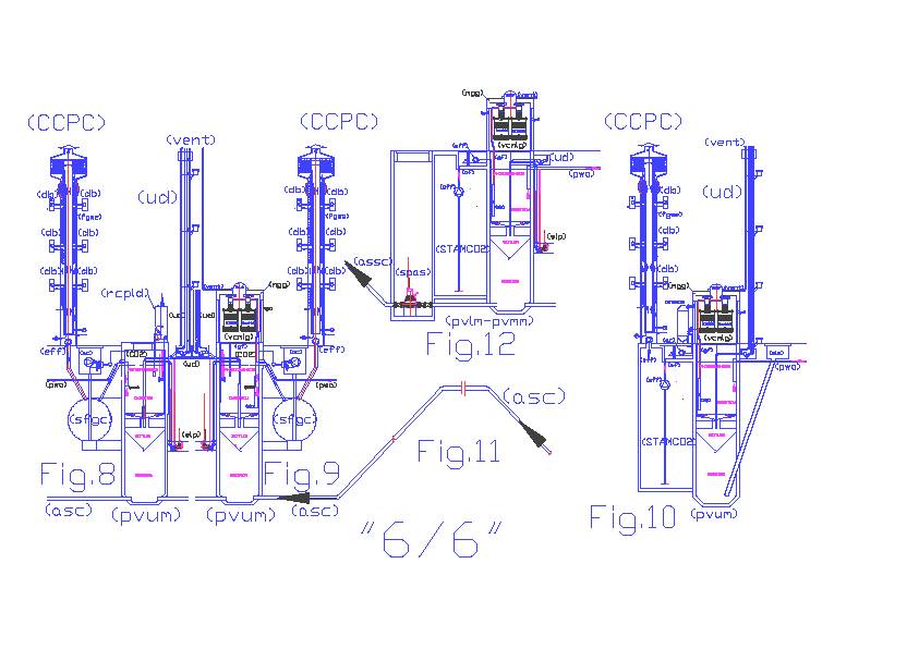
Drawing “6/6” fig. 8 shows a diagram of an original (pvum) purifying urban vertical module, expected in a global urban sewage treatment plant with “road control panel with mini limestone dosing hopper incorporated”(rcpld). This system can be used in global, urban purification, where there is no space on the surface to achieve the solution shown in fig.9 and claimed in this “PCT request”. In fact, (rcpld) can be advantageously replaced by a (mgg) “mini green house glazing” incorporating a section (vcmlg) vertical covered mechanized limestone greenhouse, superimposed on the (pvum). This system is more efficient in local purifying air and water, which is made alkaline by neutralizing CO2 without consuming calcium oxide. In urban areas the system Gued + GSPDPTC, locally, works in the following way: The chimney catches the exit air pollution from boilers and furnaces, having purified the fumes with the electrostatic filter and recovered heat to enhance the thermal performance of domestic boiler (db), the fumes are released in “settling flue gas collector” (sfgc) from which the mixture of air and CO2 through various “air filters” and “air compressors”(ac) compress it in “storage tank” (STCMCO2) and in a network (CMCO2) from which they can fetch both sections of oxidation of local (pvum) that the VSBs basins of oxidation (wba) and (wbp) that exploit the pressure and the oxygen to oxygenate the water, while the CO2 issued by oxygenated waters, forced to climb the local greenhouses and VSB (vcmlg), is absorbed to produce carbonates in the same waters that fall within their respective basins. In (pvum) it can also consume the nutrients, such as phosphorus and nitrogen by means of photosynthesis permitted by stagnant, oxygenated and lighted surface, since the treated water forced out of a tube going up to at least 100 cm to reach the level of overflow. Even in (pvum) waters are alkalized in the greenhouse by touching trays (wot) and crossing the baskets filled with calcareous material (cwhb) of (vcmlg), although everything is in miniature, in (pvum) modified happen the same purification processes of large VSB. Fig. 10, shows that the main functions of oxidation, photosynthesis and alkalization and the flue gas purification can happen even in homes and businesses or industrial blocks from centralized purification systems, supporting chimneys (CCPC) to (pvum) with (mgg) and (vclmg), but adding a storage tank for the atmospheric mixture of air and CO2 (STAMCO2), storage tank mixture of compressed air and CO2 (STCMCO2) with its filtration (af) and air compressor (ac). The sludge produced by (pvum) blocks are extracted by means of a tanker truck through “sump sludge extraction” (sle) and taken to (LDDC).
Fig. 11, it simply shows that the line “anaerobic sludge collector” (asc) need not necessarily be horizontal, as shown schematically in Figure 7, but can also have detours upward or downward, provided that the pipe is always full and close to the lift pumps are installed always one-way valves that prevent the return of sludge to (pvum). As shows Fig. 7, line (asc) reaches the “sludge hopper” (sh) of (LDDC). Fig 12 shows an application very similar to Fig. 10 but used in the scheme (GMLED) “global marine and lacustrine environmental depuration” without chimney (CCPC). In fact, this figure marked with (pvlm – pvmm) “purifying vertical lakes-marine module” is connected to the network (assc) “submergible anaerobic sludge collector”
Industrial applicability. Through these engineering drawings and technical explanations it becomes evident how important and strategic it is to locate the VSB buildings in industrial and urban areas. Equally important, they must be combined with air pollution capture systems (new chimneys and new sewerage systems) for maximum efficiency because it is much easier to capture at the source and on the ground the urban and industrial pollution and to recover the energy contained in the heat before it is released into the environment. Both material and energy waste (in the form of pollution and waste heat) is recovered and used to produce new energy. This cradle-to-cradle approach that recovers wasted material and energy should prove economically viable and will spawn new sustainable jobs and industries with the caveat that Life Cycle Analysis and economic feasibility and economic impact studies need to be carried out. At the industry level, these plants are not a venture in commercial industrialization, because these are large scale structural works which require government leadership to initiate. On a technical level , effective and widespread industrialization of environmental protection has not been achieved because there has never before been an integrated design such as VSB and it’s subsystems, in which the best competing technologies in civil construction, industrial, agricultural, biological and applied chemistry have converged into a viable solution. VSB and it’s subsystems, if implemented properly would prevent CO2 and aerosol emissions from the largest fixed fossil fuel sources -fired power plants, incinerators , steel mills , cement factories capturing the emissions and channeling them through limestone scrubber (VSB) to purify the fumes. These works are structural, technological and industrial at the same time. The water purifier function of the VSB also has a social function, but are more complete than existing water purifiers, as current water purifiers do not bother to even purify the air or to alkalize the purified water. In fact, the current purifiers do unnecessary work to combat global pollution, since working in the open air, they do not emit CO2 into the atmosphere alkalinizing that purify the water, forcing the receiving water bodies to produce eutrophication. This further wastes resources and energy and results in new and irreversible emissions of CO2 and methane leading to more global warming. The buildings (VSB) in addition to industrial and urban applications illustrated above, can also serve to replace artificial water bodies that have been created to prevent summer droughts. In fact, the existing reservoirs, located upstream of the areas to be irrigated, without spare parts of water, are a source of eutrophication and often produce disasters and floods when they are surprised by sudden torrential rains while the reservoirs are still full. It would be more useful and safer to have a system such as (VSB) that buffers and accumulates water in vertical ponds with a few inches of water which let in the light and therefore the water cleans car with photosynthesis producing digested sludge and therefore contribute to energy production. Such a system also cleans the water of hazardous sediments such as heavy metals and arsenic that are accumulating in the groundwater. Because they are downstream to the water flow, parallel to it and raised in vertical buildings, these accumulations of water would not pose any danger in the event of flooding. They also improve water quality, prevent eutrophication, dissipate the heat generated by thermal power plants and thermal plants, and act as logistical support to the intensive production of micro algae in separated closed circuits all without producing pollution. These industrial and social applications would create many new job opportunities.
Luigi Antonio Pezone