COP 27 SUSTAINABLE DESALINATION UNWANTED BY SCIENCE, GOVERNMENTS AND MULTINAZIONALS
I publish this article on the occasion of COP 27, which takes place in Egypt from 06 to 18 November 2022, which, like all African countries, has always suffered from the lack of fresh water for agriculture and civil and industrial uses. This plant in the following description is a patent filing dated 07/06/2016, it is described in a more complete version to also combine it with the creation of artificial islands and artificial welling. Obviously, on planet Earth no COP and no government has ever thought of creating artificial islands and artificial welling which are essential to combat ocean acidification and increase food production with the production of natural fish. In fact, today fish is produced by means of natural welling only along the coastal areas which represent only 5% of the sea surface. However, if for unknown reasons world governments do not want to carry out artificial welling, it is not certain that desalination cannot be carried out on its own without going into the depths of the sea to raise carbonates. Desalination can be carried out in any coastal area of the earth to send desalinated water to desert areas that are increasing throughout the planet. Certainly the desalination described by the undersigned, being energy autonomous, is cheaper, more sustainable and with immense capacity to carry water than the current filtration with membranes, which requires high maintenance costs and high energy absorption. Obviously, since the proposed plant is also a low-cost electricity producer, we can use this electricity to heat the water in pressurized autoclaves, raise it, condense it and mix it in the upper basin with the desalinated water with ion exchange in order to have water containing the right amount of mineral salts useful for agriculture and drinking without suffering the current very high costs of desalinated water. the current trade of patents, one-way, between scientists, researchers and public inventors towards multinationals has prevented the development of large public utility inventions that exploit interactive principles such as artificial welling vertical desalination with ion exchange resjne, autonomous energetically for means of submerged hydroelectric power. Today we pay the consequences by paying useless and harmful fuels, without being able to defeat world hunger and drought. The planet is moving towards self-destruction unable to develop the next phase which would have been compressed hydroelectromagnetic energy which could allow to add together the thrust of Newton and Lorentz. With these two thrusts produced at the temperature of the earth’s environment, we could also go into space without fuel, storing the energy source (compressed air) and the energy carrier (water) in the means of transport. By endlessly recycling air and water, integrating losses with photosynthesis, the carbon cycle and the capture of interstellar dust, allowed by the future interactive global linear motors, resulting from an in-depth study of the sumptuous hydroelectric used by the undersigned as an energy source for production of artificial welling and sustainable desalination unwanted by science, governments and multinationals. Obviously, those who have not believed in simple and sustainable inventions such as artificial welling and energy-independent vertical desalination, cannot believe even in space ones, not for scientific problems but of alliances of those who hold world economic power, which have nothing to what to do with science. In fact, science and research are based on multidisciplinary experiments. Interactive energy and purification applications have not collected even a single euro of world funding because no one wants to investigate thoroughly in this direction; neither public science nor that of multinationals, as if the planet Earth had already reached the maximum of scientific, technological, legislative and economic perfection. Instead, we are at the year zero of interactive discoveries not only of atoms, but above all of molecules, as demonstrated by the rhyme of SPAWHE and the map of inventions not realized by the world ruling class.( https://www.spawhe.eu/the-spawhe-rhyme-and-the-map-of-the-website/)
Floating system, hydroelectric, desalter, extractor of calcium and carbon from marine deep water.
Italian demand patent N. 102016000058018 del 07/06/2016
Abstract
The state of the art in the development of desalination and demineralization treatment of marine and brackish water has been affected, along with industrial systems, purification, energy, food and protective of the environment, the absence of synergies between the pumps and hydraulic turbines and from the incorrect approach with the gravitational force, which must not be won by the hydraulic lifting but sustained, with one-way movement of water, especially in the gravitational direction, in the sea, in large basins, in open tanks. With simply overturned pumps coupled to the turbines can produce low-cost all the energy you need; continuing the descent and ascent of water in deep waters, for the venturi effect, we can suck and lift small percentages of deep water with high calcium and carbon percentage solubilized in them, that arrived at the surface, producing phytoplankton and alkalinity, increasing the abundance of fish and combating acidification and global warming;
while on the floating platform, made with extruded and ribbed tubes made of low density polyethylene, blown in them polystyrene foam to make them unsinkable, with the triple synergy between the dual fuel pumps, turbines and the marine water recycling, by applying known hydraulic principles for centuries, as that of communicating vessels, the laws of Bernoulli and Pascal, placing, strategically, the electric double suction pump between a high positive hydraulic head and the turbines, we can desalinate large quantities of water, simply transforming a vertical tube in a ionic exchanger and recycling pipes and mixing in the energy producers, while the anionic and cationic synthetic resins, circulating contained in perforated polyethylene spheres as sieves. These spheres, floating climbing ion exchanger and descend for gravity emptying water in downhill tubes. By means of diverters change the path compared to the flow to be immersed in the washing tanks and regeneration of the resins, and reinserted again, indefinitely, in ion exchange circuit without interruption of the desalination cycle and energy production and without costs for heating the water or replace the membranes. If we want to exploit the immense riches of the sea, floating solutions have no alternative. The systems must be designed supported from above, since it cannot exist electromechanical equipment that can work to the abyssal depths. The sustainability of global systems is not only based on high technologies and special materials but above all on the physical basic principles, chemical, hydraulic and mechanical.
Description
The scope of this invention is the exploration of new sustainable plant systems for survival for the human species in the sea. The floating solution has no alternative, since no electromechanical equipment that can work to the abyssal depths.Barely resisting homogeneous materials such as steel. Therefore the plant must be lowered and supported from above, the water heavier materials, such as steel will work in traction, contrary to when it occurs in applications realized at atmospheric p ressure, where the materials work by compression, by downloading all the forces on support bases. This is a new way of designing systems which has advantages and disadvantages. For myself, are a lot more advantages. In fact, this plant is the core around which men will develop small or large human agglomerations in oceanic areas, fully autonomous from the energy and food point of view. We all know that offshore the oceans life forms of phytoplankton and zooplankton are very slim because life in the marine waters grows mainly along the land coast, where, because of the winds, waves and underwater currents are generated updrafts that bring to the surface the nutrients bound in the seabed, especially rich of organic and inorganic carbon. These nutrients, brought to the surface, producing a superficial fascia of phytoplankton by means of photosynthesis, which constitutes the food of aquatic animal organisms; therefore, in the same area it is also spontaneously creates the so-called zooplankton of various sizes formed by microorganisms (unicellular algae, protozoa etc.), larvae, small animals (such as crustaceans that form the krill), but also organisms of a certain mole like jellyfish and pluricellularial algae (such as sargas). The set of plant living beings and animals form the plankton, which is characterized by a high specific biodiversity rate from which they draw the life also fish species more.
To the Wide of the oceans, although the seabed there are huge stores of carbon accumulated over billions of years, the rise of carbon and precipitated calcium millennia can not occur spontaneously due to great depths, so you need this set of inventions, especially, considering that over areas off the oceans are not subject to high and tsunami waves. In fact, the frequent earthquakes that occur in the deep sea, are rarely perceptible in surface water, if we have the foresight to realize these works at a suitable distance from the coast. The translation of the word “tsunami” by the Japanese, means “wave in the harbor.” It is a series of waves which are generated as a result of sudden movements of the seabed due to earthquakes, underwater volcanic eruptions, landslides, meteorite impacts. The most devastating Tsunami are caused by vertical movements (lifting or sinking) of the earth’s crust along faults and edges of the ocean shelf. Considering that with current technology we can achieve unsinkable and stainless frames of plastic and mounted on them other technologies that produce energy, desalinate and potabilizzano the waters, these inventions may begin the colonization of ocean space they occupy 71% of the earth’s surface.
In fact, once solved the energy problems and desalted water, for the construction of the islands, we have sufficient energy to develop comfortable and light homes. But if we also think the technology used for the construction of the Hanging Gardens (posing the land on plastic crawl spaces covered with filter cloth), we could also bring the cultivation of the above-ground vegetables and have immense advantages, with a capacity of vegetable food and fish production now unimaginable. If we use the greenhouses, productivity, already tested, it is higher than 50%, while the desalinated water can be recycled and purified, without polluting the land flaps. But in this patent application we are concerned only the central core which produces the initial state of life, which does not exist today, but paradoxically, it could also be a better life than the one we live in metropolitan hives, not being able to imagine on these islands heavy skyscrapers and heavy vehicles that pollute the environment. However, we can imagine a life with all the technological comforts, air, water and nutrition, most of the best land and less danger of natural disasters.
So, this synergistic system focuses on four sustainable systems not yet realized on planet Earth:
1) The modular floating and sustainable system by means of extruded polyethylene pipes and reinforced.
- The lifting system of calcium and carbon dissolved in the ocean depths.
- The production system of hydroelectric power from static waters.
- The sustainable system of vertical water desalination by means of ion exchange, coupled to the energy production during the process.
This vertical system allows to have the desalinated water produced in the highest point of the system to distribute it at a considerable distance by gravity to artificial islands, which will develop around these plants, which form the heart of new industrial and economic activities, connected with floating roads.
The starting point for the construction of this system is the floating construction of Fig. 1 from which comes a hydroelectric synergistic system, water maker, calcium and carbon extractor from the deep waters of Fig. 2
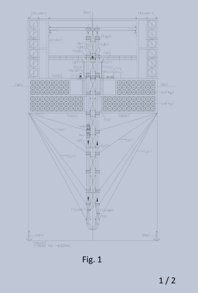
Legend: (apos) abyssal plain ocean seabed = fondale piana abissale oceanica; (bc) bridge crane = gru a ponte; (bcb) bracket cross bracing = staffa per controventatura; (br) bracing = controventatura; (cb) clamp brackets = staffe a morsetto; (dt) descent tube = tubo di discesa; (f) filter = filtro; (fsp) flange for support pipe = flange per supporto tubazioni; (hc) hydraulic cylinder = cilindro oleodinamico; (hcb) hydraulic clamp brackets = staffe a morsetto oleodinamiche; (hcbf) hydraulic clamp brackets fixed on supporting base platform = staffe a morsetto oleodinamiche fissate sulla piattaforma di base portante; (ih) immersion hole = foro d’immersione; (itia) intubate turbine with incorporate alternator = turbina intubata con alternatore incorporato; (ls) loft in steel = soppalco in acciaio; (mftp) modular floating tube made in polyethylene = tubi galleggianti modulari in polietilene; (na) navy anchor = ancora marina; (osip) overturned submergible intubated pump = elettropompa sommergibile intubata capovolta: (othcu) oil tank and hydraulic control unit = serbatoio olio e centralina oleodinamica; (sbp) supporting base platform = piattaforma di base portante; (sfep) special flanged end pieces = pezzi speciali flangiati di accoppiamento terminale; (ssbc) support structure bridge crane = struttura di sostegno gru a ponte; (tvdwi) throttling venturi deep water intake = stozzatura venturi per aspirazione acque profonde; (tcpwr) transportable chassis with many electric winches for the descent of the ropes = telaio trasportabile con molti argani elettrici per la discesa delle funi; (ut) uphill tube = tubo di salita; (wl) water level = livello acqua.
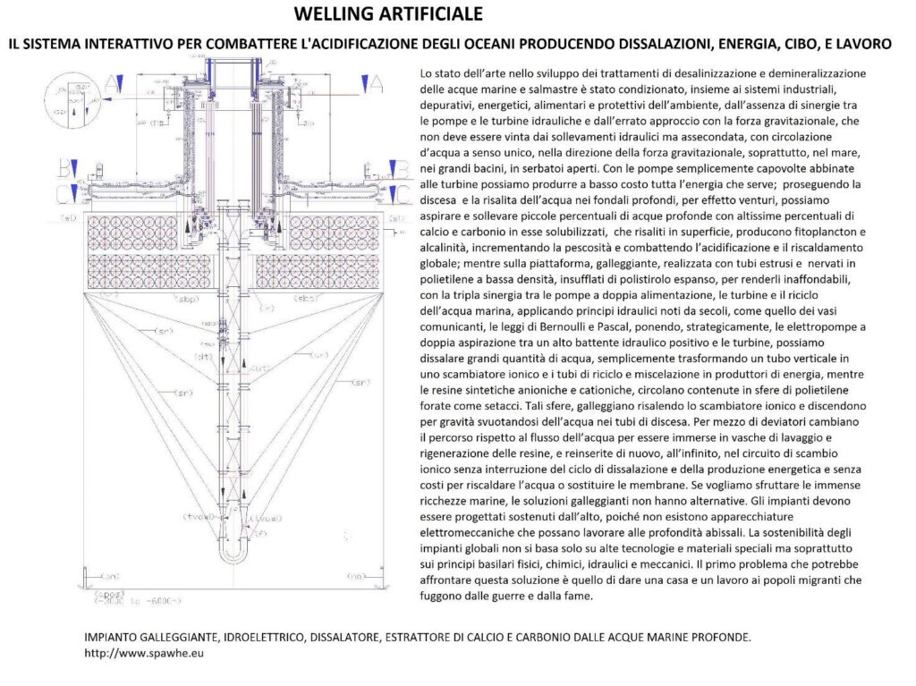
Fig. 2
The following legends integrate the legend of Fig 1, as the desalination plant is mounted on the floating structure of Fig.1 which supports the plant designed for the extraction of calcium and carbon from the deep waters, after mounting the underlying pipes and dismantled the construction site equipment.
Alphabetic legend.
(A) arrival basin of salted water; (B) salt water inlet filter with built-in check valve; (C) Water recirculation tube and dynamic or kinetic pressurization of the electric pump; (D) Nominal upper basin level; (E) washing and regeneration circuit of ion exchange resins; (F) upper reservoir mixing and overflow desalinated water; (G) Mini implant of deionized water production; (H) desalinated water storage basin; (I) desalinated water distribution network; (L) demineralized water accumulation tank; (M) regenerating liquid tank; (N) Entrance descending water; (O) exit water with calcium and carbon.
Numeric legend:
(1) overturned dual supply pump on the suction side; (2) submerged turbine with incorporated alternator; (3) nominal level of the water basin to desalinate; (4) pipe for supplying water to desalinate; (4.1) special piece for introduction spheres with resins in the ion-exchange tube (drilled in the lower part); (5) tube of ion exchange; (5.1) perforated truncated cone embedded in the tube 5; (5.2) special piece to eject spheres from the tube 5 (perforated on the entire outer surface and connected to the tube 6 by means of the slide 5.3); (5.3) metal sheet slide for the guidance of the spheres in the tube 6; (6) tube of descent spheres for the emptying; (6.1special piece for the deviation of the spheres from the ion exchange circuit to the regeneration circuit (drilled at the bottom for water drainage); (7) automated guillotine valves for stopping movement spheres (are always open when the minimum level probe indicates that the tube 6 is empty of water; (7.1) automated guillotine valves for stopping movement spheres (open one at a time); (8) first tunnel for immersion wash of the resins; (9) guided route of the spheres in the immersion tunnel with an open frame of stainless steel rods by ascents and descents with slides for the collection of the of the spheres emptying liquid; (10) tunnels for regeneration of the resins in immersion; (11) second washing immersion tunnel of the resins; (12) pump suction sludge from arrival reservoir; (13) electric pump suction of resin washing sludge; (14) electric pump suction of resins regeneration sludge; (15) Support frame demineralisation plant; (16) supply pipe demineralized water; (17) float valve for feeding demineralized water; (18) float valve for regenerating liquid supply; (19) motorized shut-off valve; (20) Manual shut-off valve; (21) check valve; (22) salinity control probe; (23) PH control probe. (24) minimum water level control probe of spheres emptying tube; (25) submerged agitator.
Description of calcium and carbon lift system from the deep waters.
As can be seen from FIG. 2, the water enters from the (N) in the “U” shaped tube that goes down in the depth ocean and exits (O). Thanks to the principle of communicating vessels, the internal and external pressures to the immersed pipes are the same. This not only allows you to withstand enormous pressures, but also allows you to use the weight of the water column on intubated pump, oriented downwards, to create intubate currents with very low energy consumption. In fact, by calculating the position in which we install the electric pump, under the head, do we make sure that the curve of the duct resistant and the pump curve that we insert for the circulation of water meet each other on the zero line of the geodetic head which is equal to zero (coinciding the levels of suction and delivery on the pump). Therefore, also the pressure and kinetic energies in the suction and discharge are reset each being P1 = P2 and V1 = V2 (due the water intubate column on the pump suction specially calculated) according to the relation H = 0 = (P2 – P1) / γ + (V22 – (V12) /2g. Obviously, no pump works with zero head and the pump just begins to turn, finds its point of operation with a few centimeters of prevalence, and a deviation from the nominal flow rate, which depend on the accuracy of the calculation. Another basic principle on which are based these systems is the Bernoulli theory that explains the venturi pumps that can help to suck from the abyssal depths, without mechanical a part of the water or sludge present in the seabed. In fact, the law of bernoulli states that: “If the fluid is flowing in a conduit provided with a constriction in which V1 and V2 are the speeds, S1 and S2 are the respective surfaces of the sections, P1 and P2 manometric pressures measured in correspondence of these sections, for the principle of conservation of energy is established the following relationship: P1 + ½ d V12 = P2 + ½ d V22. The constancy of the value of the expression shows that, the greater the speed difference in the respective sections and the smaller the pressure difference, and vice versa. Therefore, the effect of the pressure drop across the tube which occurs in the bottleneck, from the outside, enters the tube in which circulates the water surface, a percentage of the seabed water, which rises to the surface. This water is rich in many minerals because at very high depth, even the insoluble substances are solubilized. They are especially rich in calcium and carbon precipitates in the backdrops from the origins of the Earth. The calcium and carbon, rising to the surface, are diluted with the water surface and return to react according to the following reaction, which characterizes the alkaline balance of the water at atmospheric pressure: Ca2+(aq) + 2 HCO3- (aq). ↔ CACO3 + CO2 + H2O, reproducing the surface of the calcium carbonate hydrogen that exists only in solution: CO2(g) + H2O + CaCO3(s) ↔ Ca(HCO3)2. The hydrogen carbonate, in the right proportions makes possible the formation of calcareous shells and bone structure of the fish species, the restoration of coral reefs, and will help to restore the marine PH to the original level, before the industrial era, while the other components, especially based on carbon, create the conditions for developing phytoplankton and zooplankton. Unfortunately, the average depth of the ocean waters, in correspondence of the abyssal plains, oscillates between 3000 and 6000 m, but in return are characterized by the absence of the surface waves. This allows us to design completely floating rigs, which are anchored to the far seabed can be kept in acceptable limits its position, despite the sea currents.
On the fundamental importance are the water pumps to be used, which must be protected from the fish species of great size that could put them out of operation. For this and other practical reasons were chosen for the semi-axial and axial pumps ducted, for which work must only be dropped inside of the lifting pipes and resting on a ring welded inside the tube. But it is preferable that these electric pumps are slightly modified so that they can work on the descending side of the tubing (dt) with the suction side at the top, moreover, do not have the wide range of prevalence that we use in terrestrial plants. It ‘convenient to work with very low heads to conserve energy. The task of winning the circuit resistance is entrusted to the energy of surface water position. The power cables must exit the suction side, which will have its own lifting eye.
Assuming provide a calcium and carbon extraction installation on a seabed place at a depth of 6 km, and then, with the descent of the pipe 12 km in total (dt) and rise (ut), Dn 1400 which also it contains the electric pump in tract (dt), with a flow rate 4.000 L/sec, V = 2,6 m/sec, the load losses in m / km calculated with the formula of Bazin (1.000*4*V2/C2*D) wherein (C= 87/(1+2g/√D) and a roughness coefficient g=16, sono 4,11 m/km, for a total of 49,32 m. The pressure drops localized in 2 venturi bottlenecks with D2 = 700 mm (V2 = 10.4 m / s) is equal to 5.51 m (2*0.5 * V22/2g); the load losses in the 180 degree curve, is equal to 0.34 m (2*0,5* V12/2g), the load losses in the element of the final water outlet estimated at 0, 34 m.
Therefore, the head necessary for the circulation of 4000 l / sec in this circuit is about 55,5 m (49,32 + 5,51 + 0,34). Installing the electric pump at a depth of 54 m from the surface (55.5 / 1,025) whereas the sea water density is 1,025 t / m3, we will choose an electric pump, which works to give the required flow with a prevalence of only 0.2 m, because no pump can work at a zero head. It will be the effective hydraulic resistance of the circuit to establish the precise point of operation of the pump but always within a few cm of difference regarding the prevalence. Considering a 70% total return of the electric pump, the power consumption would be: (N=Q*H*1.025*102*0.7) = 11,5 Kw.
This plant designed for the carbon and calcium lifting can also produce energy. In fact, for example, if we install the pump under a ducted hydraulic turbine, which works with the flow rate of 4000 L / s and a pressure drop of 15 m, we do not increase the engine power of the pump, it is sufficient to install the pump and the turbine to a depth of 69 m instead of 54 m due to other losses of the circuit, calculated above. If the turbine efficiency with its alternator is 0.8, the energy produced will be 470.58 Kw/h (4000*15* 0,8/102). In fact, this circuit is totally open to the surface and with the intubation of surface water, once passed the state of inertia, in the descent phase develops kinetic energy fed continuously from surface. All the weight of the 69 m water column acts on the pump, the turbine producing the energy calculated above (that was subtracted of energy loss in the tubes (54 m). There are no energy costs for lifting water, since the water must not exceed the sea level. An open circuit is not similar to a closed circuit, for the mere fact that the dynamic pressure in the closed circuit can not renew with the entry of new water, as is the case in the open circuit. In fact, the renewal of the dynamic pressure is no more than the kinetic energy of the water surface that goes to the place of water displaced in depth. This energy can only exist if it picks up water from the surface one way and places the pump to the depth calculated to overcome the pressure losses of the pipes and the turbine with the mass of the ducted water column, which moves inside the tube , under the atmospheric pressure. At the exit of the pump and the turbine, it can be said, that the water does not have weight, not having to overcome the sea level. As written, just overcome the friction resistances, which can be overcome by increasing the positive head on the pump, without increasing the power of the engine which drives the pump. The hydraulic principles on energy conservation legislated by Bernoulli are limited to the comparison of pressure and speed of the water, showing that energy is conserved because it increases the velocity decreases the pressure and vice versa. Do not apply to open circuits, inserted in the hydraulic volumes more, feed them endlessly. In such circuits, without the inclusion of the turbine, the excess energy produced in the descent of the water would dissipate into heat by friction in the pipes and the pump outlet, together with the other load losses already calculated in the above example (54 m). This means that the principles of conservation of energy are always valid, but in a much larger system, which also includes the principles of thermodynamics and external energies, such as gravity, that participate otherwise if the mass is moving or stopped. Counts above the direction of movement, the speed, the dynamic pressure in the passage section. Nothing to do with the static pressure, which not being in motion, can also be transmitted with a small tube, but does not serve to produce energy. So, creating open energy circuits that depart from surface waters, within always filled basins, the energy balance is always positive because participating in the circuit outside forces that feed it endlessly and uses the energy of water located of the surface with respect to the pump positionIf we do not get bogged down in endless energy calculations, we just make the difference between spending and energy produced, thanking the nature that allows us to capitalize on these opportunities neglected by the advent of the industrial age.
In the present state of the technique of desalination and demineralization are headed three types of installations: by evaporation, permeation through membranes, for ion exchange. Currently, the difference between the three systems, mentioned above, makes it especially the cost of treatment. That evaporative, produces water free of mineral salts and with acid pH, therefore for the use of water is required a subsequent mineralization and neutralization of the pH.
The filtration with membranes entails high operating pressures, therefore high energy consumption and the high cost of the membranes, which periodically must be replaced.
The one with the ion exchange resins involve a complex filtration, washing and regeneration circuit of the resin, with reverse flows that involves the dispersion of apart of the resins in waste waters of the processes.
All processes are heavy on energy consumption for heating or for circulating pressurized water in filtration and regeneration systems. The operating costs are around 1.5 euro / mc with reverse osmosis plants, which are the most used, but also the investment costs are significant, being about 1000 Euros per m3 / day of desalinated water produced. It ‘obvious that with these production and investment costs, the desalinated water can be used only for potable use. It ‘s impossible to think to use it for industry and agriculture. With the solution that proposes the agricultural and industrial use will become a competitive reality also with wells and other purification systems, which are in any case forced to treat polluted water, or with scarce mineral requirements. In fact, the sea water being rich in mineral salts, If desalination becomes sustainable, can become the best natural fertilizer for land, being able to send the same water can be used as fertilizer treated tailored to the target terrain, both in terms of mineral salts that alkalinity. For transport the desalinated water to considerable distance there is no problem, because with the dual supply pumps coupled to the hydraulic turbines, also the transport and the lifting of the water becomes a source of energy, not of consumption. In fact, the key to solving many environmental and energy problems, including desalination, is to realize Hydraulic and hydroelectric circuits using otherwise the pumps and turbines.
At the state of the art the desalination system least used is the one with the ion exchange, but this system is the most suitable to be used in conjunction with the dual supply pumps and turbines, not having the necessity of high temperatures or high operating pressures than competing systems. Therefore, the high cost of the resins and of the reagents liquid, required for regeneration, can be largely compensated by low energy consumption, energy production produced by the plant and low cost required for plant, and low operating and maintenance costs. Furthermore, with the solution described below, it will also solved the problem of the dispersion of the resins in water and process liquids, being the resins contained and circulating (in water and chemical reagents) in perforated polyethylene spheres with holes pass below the size of the same. We can say, that the new solution is opposite to the current of ion exchange solutions, where the resins are stopped and the liquid passes through them, both in the reaction phase than in those of washing and regeneration. With the system proposed resins are circulating in the water and in the regenerating liquid, at low speeds, with long contact times, which provide capillaries contacts. For the circulation exploit physical principles, not energy. Over 90% of energy produced in the plant can be transferred to public power networks. Therefore, the facility is composed of a chemical part, an electromechanical and a hydraulic.
The chemistry of ion exchange.
From the scientific literature, one can learn that the ion exchange, is a process in which ions of a given species are replaced on the surface of a non-soluble material exchange (ion exchange resin) by ions of a different species dissolved in solution. It consists of two phases: cationic and anionic. In the proposed plant, which develops vertically, these stages take place separately in large diameter pipes (5) making transit at low speed an appropriate quantity of balls in polyethylene perforated like a sieve, containing granules of anionic resins or cationic in quantity proportional to salts to absorb, selected with a diameter greater than the passage of holes. The ion exchange resins can be natural or synthetic.
The natural resins are zeolites (aluminosilicates) used especially for the softening of the water and for the removal of ammonium ion.
The synthetic resins are formed from phenolic polymers which are generally in the form of small spheres of a diameter between 0.3 and 1.3 mm. With a density of 1.2-1.3 kg / l. They can be of two types:
a) cell structure: translucent, low elasticity, higher capacity;
b) macroporous structure: matt, high porosity, lower capacity;
the basic structure of the two types is however identical both being obtained by copolymerization. The realization of synthetic resins is generally through a process of copolymerization between styrene and divinylbenzene. Styrene has the resin matrix function, while the divinylbenzene serves to give consistency to the resin. The main properties of ion exchange resins are:
– the exchange capacity is expressed in meq / L or eq / kg. It is defined as the amount of an ion exchange resin that can lead.
– The size of the resin spheres: the importance of the dimension lies in the fact that the kinetics, and the rate of ion exchange columns is a function of the same. In general the rate of ion exchange is inversely proportional to the square of the particle diameter.
The ability of stated exchange of a resin varies according to the type and the concentration of substance used to regenerate the resin. Generally, the exchange capacity of a synthetic resin varies between 2 and 10 eq / Kg resin, while the zeolites have a cationic exchange capacity ranging 0.05 to 0.1 eq / kg resin.
Often the exchange capacity of the resins is expressed in terms of grams of CaCO3 per m3 of resin (g / m3) or equivalent grams per m3 (g eq / m3).
The level regenerative: is the quantity of regenerant (HCl, H2SO4, NaOH) considered at 100% required to regenerate a liter of resin. It is expressed in grams per liter of resin regenerant.
The total capacity of exchange: It is the concentration of active sites per unit of measure. It is for unit of volume (Eq / liter) or weight (Eq / g) and is a parameter specified in the data sheets of the resins.
The operational capacity of exchange: is the quantity of ions (Eq / liter or g CaCO3 / liter) that a given exchange resin under specific working conditions in which it is used.
The process schemes vary depending on the objective of the treatment to be carried out.
Some classic treatment achievable with the ion exchange resins are: softening, decarbonation (partial demineralisation) Full demineralization, removal of heavy metals specify, but substantially, ion exchange, such as ultra filtration, if it becomes sustainable and energy is also a great third party purification system.
As initially said the ion exchange generally involves the exchange of an ion present on the functional group of the resin with an ion of the same charge present in solution.
At the state of the art are distinguished five types of synthetic ion-exchange resins:
1) strong cationic resins, 2) weak cationic resins, 3) strong anionic resins, 4) weak anionic resins, 5) chelating selective resins for heavy metals.
– The strong cationic resins behave in a manner similar to a strong acid and are highly ionized in both their acid form (R-SO3H) that in that saline (RSO3Na) in a wide range of pH values.
– The weak cation resins have a weak acid functional group, typically a carboxyl group (COOH). These resins behave as weak acids, and as such have a low degree of dissociation.
– The strong anionic resins are strongly ionized due to strong basic groups such as the hydroxyl anion (OH) and may be used throughout the pH range. Thanks to the hydroxyl OH group are often used for the deionization of the water.
– The weak anionic resins are carriers of the weak basic groups and therefore have a degree of ionization depends on the pH, generally ionize in narrow pH fields.
The selective chelating resins for heavy metals behave as strong cationic resins, however, presenting a high degree of selection in the ability to chelate heavy metal cations.
Note that the ion exchange reactions are real equilibrium chemical reactions and as such reversible. In this regard, the working cycle of a resin is composed of two stages: – the operating phase also called “exhaustion” during which the reactions go from left to right (that is, it has the replacement of the ions present on functional groups with those present in the solution) and that end with the saturation of all functional groups. This phase, in the plant in question, takes place in the ion-exchange tubes (5).
– The step of charging also called “regeneration” in which the reaction is allowed to proceed from right to left by reloading the functional groups with originating ions of the resin. In the proposed solution, the regeneration takes place by passing the polyethylene perforated spheres, with the incorporated resin, in tunnels immersion of regenerating liquid and washing (E), consisting of:
– Basic solutions, typically basic substances type NaOH, NH4OH, in the case of anionic resins. In that case, recharge the resins with OH- ions.
-Solutions acidic, typically based on strong acids (HCl, H2SO4) in the case of cationic resins. In this case recharge resins with H + ions.
The high concentration of H + ions and OH-, in the two cases causes, for the law of mass action, the displacement of the reaction to the left resulting in charging of the resins and release of the ions in solution which in the exhaustion phase (5) were It has been absorbed by the resins. This obtains an eluate generally composed of various metals chlorides (if using HCl, the H + ion charging the resin, while the Cl- ion binds to the cation released from the resin) or the various salts of sodium in the case of using NaOH ( the ion OH- charging the resin, while at the Na + ion binds to the anions released in regeneration from the resin to give sodium salts).
ES.: Ca++ + 2HCl → CaCl2 + 2 H+; SO4— + 2NaOH → Na2SO4 + 2OH.
The ion exchange resins for the fact that exchange hydrogen ions (cationic) and idrossilioni (anionic) are more properly defined cationic resins in acid cycle (RH) and anion resins in the basic cycle (R-OH), owing to the characteristics of the released ions which make the acidic or basic water.
Below are some of the ion exchange reactions for synthetic resins:
Strong cationic resin:
R-SO3H + Na+↔ R-SO3Na + H+; 2R- SO3Na + Ca2+ ↔ (R-SO3)2Ca + 2Na+.
Weak cationic resins:
R-COOH + Na+ ↔ R-COONa + H+; 2R-COONa + Ca2+ ↔ (RCOO)2Ca + 2Na+
Strong anionic resin:
RR’3NOH + Cl–↔ RR’NCl + OH–.
Weak anionic resin:
RNH3OH + Cl– ↔ RNH3Cl + OH–; 2RNH3Cl + SO42-↔ (RNH3)2SO4 + 2Cl–.
Example of exchange and regeneration.
Removal of sodium ions (Na +) and calcium (Ca2 +) from water using a strong cationic resin. Reaction: R- H+ +Na+→ R -Na+ +H+; 2R– Na+ + Ca2+ → R2–Ca2+ + 2Na+
Regeneration:
the regeneration is carried out with hydrochloric acid (HCl) and sodium chloride (NaCl)
R–Na+ + HCl → R–H+ + NaCl; R2–Ca2+ + 2NaCl → 2R–Na+ + CaCl2.
The selectivity of a resin, namely the fact that an ion present in solution in active sites, exchange with those rather than another, depends on the nature and valence of the ion, the type of resin, by its saturation, as well as by the concentration of one specific ion in solution. Generally such selectivity remains valid in a narrow pH range. Typically the selectivity scale or if we want to affinity of the cationic resin exchange turns out to be:
Li+ < H+ < Na+ < NH4+ < K + < Rb+ Ag+ Mg2+ < Zn2+ < Co2+ < Cu2+ < Ca2+ < Sr2+ < Ba2+ ; while for the anionic resins it is: OH– <<< F–< HCO– < Cl– < Br– < NO3– < ClO4–
In current of ion exchange systems the operating phase provides, generally, the passage of water in a resin tank filled and a flow rate of water that must be kept within certain limits to ensure adequate exchange times. The characteristic data are highly variable in function of the amount of salts and ph: operating flow rate of between 5 and 50 liters / h / liter resin. It ‘very difficult to manage and control the complete process, especially if you need to desalinate large flow of water. Even the regenerative phase, currently, it is not easy to handle. It is divided into three sub-phases.
a) Washing in countercurrent (backwash): water in upward flow, the flow velocity equal to 10-15 m / h, 50-70% of the expansion of the resin bed. This washing serves to eliminate any preferential paths formed during the exchange phase and to remove impurities that may have possibly formed in the bed during the exchange phase. The duration of this phase, in existing plants, is around 15 minutes.
b) The regeneration can be acidic or basic depending which relates to a cation exchange resin or anion respectively. The solutions are dilute solutions of acid or base whose percent dissolved depends on the strength (degree of dissociation) of the same. For example, to recharge a cationic resin can be used acidic solutions such as:
5 – 10 % di HCl with flow of 3 -4 l/h/l of resin.
1 – 3 % di H2SO4 with flow of 10 – 15 l/h/l of resin.
c) Final washing which is carried out with demineralized water in a down flow in two phases:
a first phase to the flow of the regenerative phase to wash the residual acid;
a second phase to the operating conditions for a total volume of water equal to 6 – 9 volumes of resin.
The new electro-mechanical and hydraulic systems of ion exchange.
The long introduction, above, who summarized the state of the art of chemical and physical processes that govern the complex ion exchange system is essential to understand the reasons why it is born this invention. In fact, the work cycles of the current systems that use the ion exchange are the starting point for the design of these new plants, which must not distort the basic principles, but should only make them cheaper, especially, by combining the production of energy hydroelectric, low cost, that sold to operators, of fact, lowers the cost of desalination. In fact, hydropower produced without the classical hydraulic jump, is much cheaper than the current hydropower, not requiring the construction of dams and reservoirs. Just only the utilization of positional energy of water placed in the high position of a water system remained always full to take advantage of favorable hydraulic condition for energy purposes. Therefore, the plants, with ion exchange, combined with the production of energy, in addition to the desalination and demineralization, may also have other cleansing applications, so that even the sweet water, in many cases, even when they are extracted from the subsoil, must be deprived of undesired substances because of the numerous infiltration due to the chemicals used in agriculture, in industry, in urban activities, infiltration of solvents and radioactive metals freed near drilling with the system of fracturing water with solvents and inert materials at high pressure. Certainly, even the ultra filtration can be combined with the production of hydroelectric energy, reducing operating costs, but most of the energy would be consumed in the same facility, while the cost for the replacement of worn membranes would not be solved. In addition, it is necessary to clarify that state of the art, not desalination sea water but only brackish waters because desalination the sea water would cost about 3.5 times the current costs, which already are not sustainable for large jobs ladder. In fact, in the process for reverse osmosis, the water by desalination is put in communication with fresh water through a membrane permeable only to the solvent; applying on the side of the saline solution a pressure higher than that which is generated by osmosis, it reverses the normal direction of spread and the solvent tends to leave the solution with higher content of salts. The process is not yet used for the desalination of sea water, since, being the osmotic pressure between sea water (salinity medium: 35 g / l) and distilled water equal to approximately 22 bar, the corresponding pressure required to obtain a appreciable flow of solvent through the membrane may even exceed 100 bar. The process is, instead, application for the desalination of brackish water with a salinity less than 10 g / l. In the same proportion they will also increase the energy costs of evaporative processes, while with the ion exchange proposed only increases the cost of the chemical additives and of the amounts of resins required.
Before starting the description of the process should bring the legends of the figures illustrating the plant.
Alphabetic legend: (A) arrival basin of salted water; (B) salt water inlet filter with built-in check valve; (C) Water recirculation tube and dynamic or kinetic pressurization of the electric pump; (D) Nominal upper basin level; (E) washing and regeneration circuit of ion exchange resins; (F) upper reservoir mixing and overflow desalinated water; (G) Mini implant of deionized water production; (H) desalinated water storage basin; (I) desalinated water distribution network; (L) demineralized water accumulation tank; (M) regenerating liquid tank.
Numerical legend: (1) overturned dual supply pump on the suction side; (2) submerged turbine with incorporated alternator; (3) nominal level of the water basin to desalinate; (4) pipe for supplying water to desalinate; (4.1) special piece for introduction spheres with resins in the ion-exchange tube (drilled in the lower part); (5) tube of ion exchange; (5.1) perforated truncated cone embedded in the tube 5; (5.2) special piece to eject spheres from the tube 5 (perforated on the entire outer surface and connected to the tube 6 by means of the slide 5.3); (5.3) metal sheet slide for the guidance of the spheres in the tube 6; (6) tube of descent spheres for the emptying; (6.1) special piece for the deviation of the spheres from the ion exchange circuit to the regeneration circuit (drilled at the bottom for water drainage); (7) automated guillotine valves for stopping movement spheres (are always open when the minimum level probe indicates that the tube 6 is empty of water; (7.1) automated guillotine valves for stopping movement spheres (open one at a time); (8) first tunnel for immersion wash of the resins; (9) guided route of the spheres in the immersion tunnel with an open frame of stainless steel rods by ascents and descents with slides for the collection of the of the spheres emptying liquid; (10) tunnels for regeneration of the resins in immersion; (11second washing immersion tunnel of the resins; (12) pump suction sludge from arrival reservoir; (13) electric pump suction of resin washing sludge; (14) electric pump suction of resins regeneration sludge; (15) Support frame demineralisation plant; (16) supply pipe demineralized water; (17) float valve for feeding demineralized water; (18) float valve for regenerating liquid supply; (19) motorized shut-off valve; (20) Manual shut-off valve; (21) check valve; (22) salinity control probe; (23) PH control probe. (24) minimum water level control probe of spheres emptying tube; (25) submerged agitator.
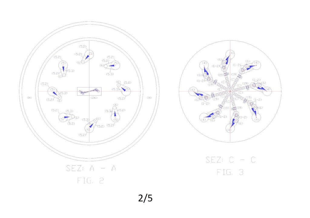
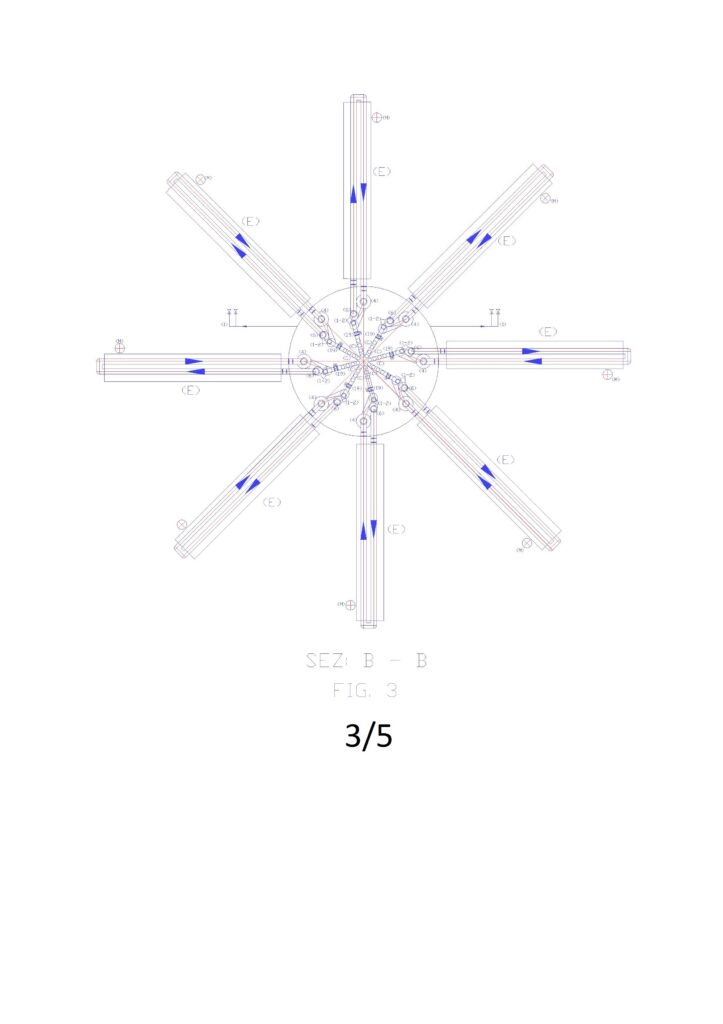
Figures 2, 3, 4, report the sections to altimetric plans A, B, C.
Annotations on hydraulic principles and fluid used.
So that it produces the maximum energy kinetic energy in a pump-turbine group, place under a head, which discharges the water in depth, within the same basin, it is necessary that the water is drawn from the highest point of the ‘ plant and arrives directly on the pump placed in the lowest point of the system. In fact, it is known that a moving body (including water), increases its force (F = m * a), both if it moves horizontally or vertically. Obviously, in the case of water, if it moves in the horizontal acceleration must provide all the pump motor, if it moves vertically, in the direction of the gravitational force, to the acceleration provided by the pump, it also adds the acceleration gravitational (g = 9,81 m/s2But it is not sufficient only to orient the pump downwards and exploit the hydrostatic head, because the mass of water that would move without the vertical intubation, would be only that is around the pump, therefore, the turbine would produce very little energy. The surface water intubation is essential to provide the entire water column above the pump energy of movement. Therefore, it is necessary to use a descent tube (c) for each pump-turbine group. On the other hand, this need is intuitive, since even the turbines that exploit the hydraulic jump to the atmospheric pressure are connected individually to the upper reservoir. Contrary to what one might think is not the flow rate combined with pressure drop to produce in traditional hydroelectric energy, but the flow of water transformed into kinetic energy (or dynamic) realized in the path that feeds the turbine (P = η*1000*Q*Hu/102).
In traditional hydroelectric energy it is not commit calculation errors because flowing the water to atmospheric pressure and not recycling it, the whole static pressure energy, reclaimed from the load losses, is transformed into kinetic energy. But the traditional hydropower should have been the exception that proves the rule, however, for the experts, it has become the rule, and no one wants to deepen the utilization of surface energy of water location within the same volume of water, which can be done anywhere without building dams and large hydraulic basins. In fact, in the case of installations always filled with water, not having, a hydraulic jump to exploit, to produce kinetic energy is necessary to take advantage of the relative position difference within the same volume of water, thus the plants and the pumps must be designed otherwise. It ‘necessary to intubate the surface water to take advantage of his energy of position with respect to the pump location and the turbine, which connected in series, function as one single machine: the pump wins the state of inertia and keep the motion in time allowing the acceleration of gravity to produce more kinetic energy than it spends the pump, while the turbine uses the total energy to produce electricity through the built-in or connected alternator. It ‘obvious that if only ponessimo the ducted pump under a swing of 10 or 20 m of water column, there being no hydraulic resistance in the flow, it would create a large hydraulic imbalance, since all the kinetic energy developed by the water column , due to the acceleration of gravity on the pump, finding no contrast, apart the friction of the water molecules, it would be dispersed into heat. In fact, the static pressure of water, to the fact that the liquid is incompressible does not oppose to the kinetic energy. Therefore, the velocity would increase in the permitted limits and the pump would be damaged in a short time, failing to control the flow of water that it would have started. Insert a turbine after the pump, in addition to being a rational energy solution is also the balancing element of the forces generated. Therefore, with the proposed system we can produce energy in the turbine by the energetic flywheel constituted by the masses in movement in the direction of gravitational force, discharging the water in the open basin, or in an open section connected to the upper reservoir, with small residual velocity at the exit of the turbine. The load loss to be calculated for this discharge is more or less the same that would have with the discharge tof he water in the atmosphere (V2/2g). It is ‘equally obvious that without the water intubation that part from the surface we could not produce the kinetic energy that is used to produce electricity, since the water that would power the pump would be surrounding the pump, equipped with only one static pressure. These are the reasons why in the diagram of Fig. 1 each pump is connected with a suction mouth to the upper reservoir and for which this tube has been called dynamic pressurization tube. In fact, the static pressure in a closed circuit can be transmitted with a small tube (Just think of the famous experiment of Pascal that with tube full of water placed vertically, smashes a wooden barrel), while in order to give at a flow rate of the water pressure dynamic (or kinetic), it is necessary that the unitary pressure is multiplied by the water passage section (10 m column of water equivalent to 1 kg / cm2). If we have a passage section of 100 cm2 and we want transmit dynamically the entire pressure of the ten meters of water column, this section must be maintained and extended considering the load losses for not to lose kinetic energy. This must cover the entire circuit path, including the body of the pump. So if we want a dual supply pump sends water fed from the lower basin (always with a positive swing) the dynamic energy of the water coming from the reservoir (F), the passage in the pump sections must be adapted to the sum of the two flows. In such conditions, at t he pump outlet we will have a single flow and a single pressure, which will approach the sum of the flow rate and the maximum inlet pressure, plus that provided by the pump, minus the pressure losses of the circuit. This application is also confirmed in Torricelli’s theory that showed that the output speed of the water to a hole made on the wall of a water tank under a hydraulic head (h) is calculated with the formula √2 * g * h, regardless of the actual depth of the tank. Obviously, this confirmation should be interpreted only as the certification of existence of surface water energy location. But to harness that energy for electricity generation in the same volume of water or in plants always full, recycling water, is necessary modifications to the pumps and hydraulic circuits currently used, since at the current state of the art, no one has done the right technical and scientific reflections. The same patent offices, in previous applications of the undersigned, have declared such applications contrary to the principles on energy conservation, not distinguishing the difference between simple and complex circuits. In fact, the hydraulic principles of the Energy Conservation legislated do not include complex hydraulic circuits made within the same volume of water, which can feed endlessly internal circuits, considering the basin always full, therefore, respecting the principles legislated. With the surface water intubation and the coupling under the head of the pumps with the turbines, of fact, are realized within the same volume of water many hydraulic systems separate from the static water, as there are pump-turbine groups realized. Each group produces electricity, by the difference between the energy consumption and spending, independently from the other groups, drawing on common energy source, which are the energy of surface water location and atmospheric pressure. The system can also produce energy by lifting water from a basin to another as long as the circuit is always full and the water to be lifted is inserted into the recycling circuit of upper reservoir by means of a feeding of a pump with double mouth placed under the head, dynamically pressurized by hydrostatic height of the upper basin on the second suction inlet.
Obviously, in a basin always full, even the static pressure is dispersed. These considerations do not need to be demonstrated with prototypes because if they were true, they would not hesitate sea currents and underwater pipelines may not discharge the water in the deep seabed with small kinetic energies. If this happens it is precisely because the exhaust pipe part of the surface, the internal static pressure and external to the tube are balanced, while the energy developed inside the tube with the insertion of the pump under the hydrostatic pressure contained in the same tube, communicating with the upper reservoir and with the atmosphere, finds no opposition, apart from the famous V2/2g.
Another authoritative confirmation comes from the famous scientist Albert Einstein, who with his theories of relativity showed that matter and energy can be considered as a unit, since the one can become the other according to a precise mathematical relationship. A practical confirmation of this statement we can find in the action of the wind can generate electricity through wind turbines but can also break the inertial balance between the troposphere and hydrosphere, creating kinetic energy in ocean currents. This, for myself, is the energy aspect underrated in the world, because even we can break this balance, artificially, by means of intubation of a small stream of water, a pump placed in the depth of the water and concentrate all ‘kinetic energy produced on the blades of a hydraulic turbine. There is no law of conservation of energy that can prevent it and no energy balance to do, except that between the energy used and that produced, because we take energy from an endless source. The difference between expenditure and energy produced is immense, in favor of the energy produced, because we are not in an isolated system as the pendulum of Newton. In fact, all the weight of the water column intubated (m * g * h) gains kinetic energy (1/2 mv2) braked by the blades of the turbine, which produces electricity by alternator connected, under the weight of the water masses conveyed on the turbine to the effect of gravity and atmospheric pressure, once moved the masses of water below by means of the pump. In fact, Einstein says that the energy provided it does not increase the speed of the body, but its mass: the body becomes more and more “heavy”. This is also reflected in the practical calculations of the prevalence of lift pumps which is subtracted from the positive head on the suction side, being considered an energy in all respects. This energy becomes even more important if instead of raising the water we use pumps to produce energy. In this case, it is convenient that pumps orient the flow of the flow in the direction of the force of gravity and atmospheric pressure. Using this system the difference between the energy used and that produced becomes huge because the surface water has the same density as water below, and therefore does not need to rise to the surface, if we are in a small basin (The water simply changes position). The energy production is huge, as realized in terrestrial hydroelectric, at atmospheric pressure, because the exit of the turbine the hydrostatic water pressure cannot oppose the kinetic energy remaining. In fact, because water is incompressible, at any depth is on the outlet, the hydraulic resistance to the output is always the same (v2 / 2g). Therefore, energy expenditure may be multiplied by a hundred, two hundred, etc. It depends only on the water column, which weighs on the pump and on the turbine.
The dual supply pumps on the suction side The dual supply pumps on the suction side, used in this system do not exist, as described above, for the wrong interpretation of the fluid dynamic principles, which have resulted in enormous waste in all areas of human activity, but are simple to realize by changing the supply of current pumps, not the construction technology of the same. In fact, by feeding the impeller from the outside by two confluences (curves or grafts with different angle) channeled internally, so that the two flows cross each other and nourish the pump impeller into four separate sectors, arranged diagonally, two fed with ‘ water to be lifted and two fed with the recycled water from the top, equipped with high hydrostatic pressure. Balancing in the above manner the hydraulic thrust on the impeller and on the bearings, and by getting its flows deep into the impeller, so that they are not in contact before being dragged by the impeller itself can transform all existing hydraulic systems from energy absorbers to producers of the same, of course, also modifying plants and inserting the turbines in series to the pumps.
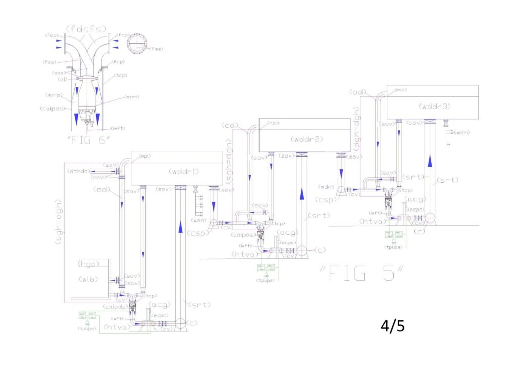
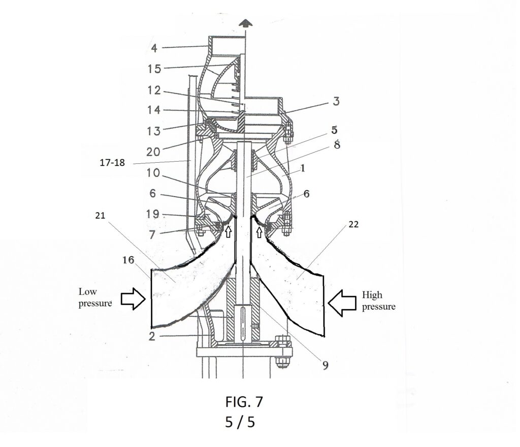
We start from the heart of a pump that is the impeller, which can produce an axial flow, radial or axial seeds and can be opened, closed or semi-closed, in function of the pump body in which is mounted. There are also pumps with twin impeller, with horizontal shafts and double feed at the same pressure, which have excellent performance, but we do not take them into account, since the pumps that we propose, to simultaneously take advantage of the hydraulic principles of communicating vessels and Pascal, who allow increments of flow rates and low energy cost pressures, they must be supplied with different hydrostatic pressures. All pumps can be changed and fed with different pressures. Obviously, with different performance and returns in function of the characteristics of the impellers that are currently mounted. With high flow and small increments of pressure will be used axial or half axial impellers, with small flow and more pressure will be used closed impellers and more precision of the workmanship, as happens in the current pumps. The important is to understand that these pumps should never work in suction but only under the head and that dividend flow which reaches into four sectors that arrive directly at the entrance of the impeller, with the rotation of the pump, in each sector is alternated l ‘ entry of water into high and low pressure, which have the same direction, therefore the flow rate with greater pressure transmits its pressure to the flow with lower pressure inside the same impeller, which as is known is designed to increase the water pressure starting from the center to the periphery of the rotor itself. Obviously, at the pump outlet we will have only a single stream with the sum of the flow and the greater pressure. This is nothing but the dynamic application of the principle of Pascal, that with current technology it is simple to implement. Figure 6 shows the change of a pump with axial impeller, Figure 7, that of a pump with closed impeller.
Description of the operation of desalination and demineralization.
The water to desalinate contained in the basin (A) (always maintained at the highest level by an appropriate hydraulic level regulator), is drawn through the filters (B) and a motorized gate valve (19) from one of the two suction mouths of the pump with double feed (1). The other suction mouth is fed from the recycling tube and dynamic pressurization (C) that comes from the upper reservoir (F). position. Therefore, in this condition, the turbine (2) produces the maximum energy allowed by the system. In any case the output of the turbine is connected to the tube (4) of wide section from which the water rises to the ion exchanger (5) where float suspended in the water of perforated polyethylene spheres as sieves in which floating of the resin granules synthetic ion exchange, selected with a diameter greater than the holes of the passage of water. Therefore, the output of the ion-exchange tube reach the upper reservoir (F), the water and the spheres with the resins. The principle for which the polyethylene balls circulate together with the water in the ion-exchange tube (5) is based on the polyethylene density which is slightly lower than pure water (950 kg / m3). So assuming to realize holed spheres that weigh 950 grams, equipped with a threaded plug, we can insert up to 50 grams of resin that has a density of 1.2-1.3 kg / the dry, in order to circulate freely in the resins’ pure water and having them float in the marine. Whereas the volume of wet resin increases by 50 – 70%, the specific weight of the resins becomes (0.7 to 0.8 kg / l), therefore, we can assume that the resins of the float inside polyethylene spheres, also in pure water. This condition is ideal for the ion exchange with the volume of water contained in the sphere, certainly more effective than a flow of water that passes through a compact bed of resins. This implies a considerable saving on the amount of resins required.
To properly operate the plant, in the basin (F) the spheres that lead the resins must be emptied of water and sent to the regeneration circuit (E). Therefore, in the tank (F) as you can be seen from a detail extracted from “Fig. 1 “, and in plan view in” Fig. 2 “, a special piece (5.2) is upwardly connected to the ion exchanger (5) drilled on the entire outer surface and connected, by connection slide in plate of steel (5.3) to the entry hole of the descent pipe and emptying of spheres (6), placed above The overflow altitude of the tank F (D). Therefore in the tube (6) the spheres are emptied of water and carrying the resins only. The water recovered from the spheres descent tube (6) and is reinserted in the plant through the check valve (21) and a motorized gate valve (19) from one of the two suction mouths of another pump with dual power supply (1). The other suction mouth is fed from the pipe (C) that comes from the upper reservoir (F). When the tube (6) is empty of water the minimum level probe (20) closes the valve (19) and open another connection (C) which also comes from the tank F. Therefore, also in this case, both suction mouths are fed with water coming from the basin F, with the maximum hydrostatic level and produces maximum energy in the turbine 2, until the water level rises in the tube (6), which detected by another sensor (20) opens the drain valve and closes that of the pipe (C). Obviously, the flush water by the spheres is essential to pass from one stage of the process to another. It can not be interrupted even when salt water enters from the suction filter (B), therefore we use two separate circuits, both equipped with pumps and turbines.
This does not penalize the performance of the ion exchange, but increases the combined energy plant performance. The desalination plant can also be realized with the recycling of the spheres and with normal pumps, but the two new products are put together to build systems with higher performance and multidisciplinary. In fact, the plant also being designed to generate energy, it is necessary the use of dual fuel pumps and always ensure, at least on one of the two connected suction mouths with a recycle and dynamic pressurizing pipe (C), by equipping both connections of a motorized interception valve (19). With this system we allow the pressurization of the pump (1), and then the energy production, also during the step of charging the water to desalinate and when there is no water to be recovered from the emptying of the spheres. The spheres, empty of water but containing the resins, accumulated vertically in the tube (6), through special piece (6.1) are transferred, one at a time, to the washing and regeneration circuit (E). In fact, by observing Fig. 1, it can be noted that the spheres by gravity are pushed against the first guillotine valve (7), which opens with the consent of the minimum level probe (20), letting through the spheres (the second valve is for reserve and it always leaves open). The spheres circuit crosses seamless the first washing (8), the regeneration (10) and the second washing (11), which take place by simple immersion, being spheres guided by a simple open frame, made of stainless.steel rods. At the end of the second wash, the spheres are pushed against the first slide valve (7), which lets it pass one at a time, as the second slide valve must prevent reverse flow of water from the tube (5). Thereforethe spheres stationed for a time between a gate and the other and after the closing of the first opens the second inserting the ball in the flow of water coming from the pipe (4) through the special piece 4.1, specially drilled in the part infer . Even the concentric cone is perforated over the entire surface to allow the passage of water without pressure losses from the pipe (4) to (5).
The entire system must be managed globally, both from the chemical point of view, to dilute the incoming water salinity, both electromechanical and hydraulic, to exploit the available hydraulic pressures, and thus produce the maximum energy. In steady state operation, the desalinated water is produced on the base of the lowering level of the water accumulation tanks (H), which by gravity distribute water to the consumption network (I). When these require water, the precedence of the sectors to be fed with priority from the suction filter (B) depends on the water quality detected by the control probes (22 -23) of the salinity and pH, while the potential of the plant depends by the number of ion exchangers, the size of the same, the amount of resins in circulation in the spheres. As regards the electrical energy produced by the plant, as seen from Fig.1, each ion exchanger is equipped with two pump-turbine groups, which can have any size, working with very low operating pressures. In Figures 2, 3, 4, it is seen that the proposed plant as an example is divided into eight sectors, but may also be more or less, according to system requirements and the required flow from the territory. Each sector, as mentioned in the introductory phase, can be specialized in the following versions: 1) strong cationic resins, 2) weak cationic resins, 3) strong anionic resins, 4) weak anionic resins, 5) chelating resins selective for different heavy metals. So, we have a wide managerial choice to desalinate and to purify, producing and distributing energy instead of consuming it.
The radial arrangement of the vertical ion exchange tubes (5) and relative regenerations, around the storage tank and recycling (F), allows to mix the treated flow, by each plant, also helped by some submerged agitator (26). It ‘important above all, the fact that the desalinated waters leave from the highest point of the system. Therefore, they can be transferred to tens of kilometers of distances by gravity. Suffice it to say that a piping DN 1000 with a flow rate of 1000 L / s and a water velocity of 1.27 m / s according to the tables calculated with the formula of Bazin-Fantoli has a load loss of only 1.5 m / km. So with a plant height of 15 meters, we can transfer the desalinated water at 10 kilometers away.
But what is equally important is the fact that using the same hydraulic system in the subsequent lifting equipment, with dual supply pumps coupled to the turbines (as shown in Figure ), the desalinated water can be transported away to supply other floating villages.
Luigi Antonio Pezone